At a time when the first successful submarine cable has been laid across the Atlantic, and a second has been recovered from depths once thought unfathomable, many persons will be led to consider how far these great achievements, following on failures almost as great, have been due to mere good fortune, or to a real progress in knowledge. The object of this article is shortly to explain the advances which have lately been made in theory and practice by those who carry out the manufacture and submersion of telegraph cables. To make this explanation intelligible to the general reader, it will be well first to describe what a submarine cable is, and what are the functions it has to perform, although probably few who read this article will be so entirely ignorant of the subject as to suppose, with an ingenious correspondent of the English Mechanic and Mirror of Science, that the copper conductor is a long rope which slips backwards and forwards inside a gutta-percha tube, so as to ring a bell in America when pulled by the clerk in England.
The electrical conductor in a cable really is a copper rope in almost all cables now made, though a single wire is still sometimes used; when small, three wires generally form the strand; when larger, seven wires are used. Single wires were first employed, but they sometimes broke at a brittle part, and when large, were inconveniently stiff, tending to force their way out through the insulating sheath of gutta-percha. The seven wires of the strand never break all at one point, and the fracture of any one produces no sensible effect on the conductor as a whole; for although the strength of a chain is limited by that of its weakest link, the conducting power of a wire or strand is in no way limited by that of its smallest section. The large Atlantic strand might be cut in two and joined by a short fine wire barely visible to the eye, without any difference being felt in the rapidity with which signals could be transmitted, or in the magnitude of the currents observed in the cable. The thin wire would produce no sensible effect, unless the length over which it formed the exclusive conductor bore some sensible proportion to that of the whole cable. Six, therefore, of the seven wires of a conductor may be broken in a thousand places without any injury to the cable, provided any one wire at each spot remains not wholly broken; nor is it, of course, necessary that this one wire should always be the same. Of course the seven wires forming the strand act as one conductor, and transmit only one message at a time.
The interstices between the several wires are filled with an insulating varnish known as Chatterton’s Compound. The object of this varnish is to prevent the percolation of water along the strand, should any water ever reach it, and also to produce a more perfect adhesion between the strand and the gutta envelope, so that it becomes very difficult to strip off the insulator, even should it be cut or abraded. In older cables it was by no means difficult to pull the insulator off the copper in the form of a gutta-percha tube, and in great depths water was very generally found to have penetrated to the copper throughout its entire length. This was not necessarily fatal to the cable, for the water inside might be quite well insulated from the water outside, owing to the extreme minuteness of the pores by which it had gained access to the interior; but this water was the cause of serious difficulty and danger in joining a fresh piece of cable to an old one during repairs, and it was also probably dangerous by its tendency to produce an oxidation of the copper conductor. In cables as now made, there is no space for the water to lodge, and no water is ever found between the insulator and the copper.
The insulator employed in every cable of importance hitherto laid has been gutta-percha. The copper strand is passed into a vat of semi-fluid percha, and is drawn through a die of such size as to allow a convenient thickness of insulator to be pressed out round it. This first layer of gutta-percha receives a coat of Chatterton’s Compound, and the process is repeated until the copper is covered to the specified thickness by a succession of alternate layers of gutta-percha and compound. Three or four coats of each material are generally used; the largest wires with their insulating cover are nearly half-an-inch in diameter, the smallest in practical use for cables are about a quarter of an inch in diameter; but it is quite possible to cover in this way copper wire no thicker than a hair. The dangers encountered in this part of the manufacture are, impurities in the gutta-percha; eccentricity of the conductor in the insulator, leaving a dangerously thin coating of the latter; and, lastly, air-bubbles which may lodge in the insulator unperceived, and do serious injury. In time, water is certain to penetrate to these air bubbles; it becomes partly decomposed, the gas generated bursts the bubble, and exposes the copper to the water. The slight leak thus formed is, by the action of the battery used in signalling, easily developed into a very serious fault. Fortunately, the manufacturers have been able almost, if not wholly, to prevent the occurrence of these dangerous cavities.
If the cable is to have only one conductor, as is the case in most long lines, the insulated wire is served or wrapped with hemp or jute, which acts as a padding between the gutta-percha and the outer iron wires used to give strength. This serving used to be tarred, but Mr. W. Smith pointed out that the tar was occasionally squeezed into small faults, and was a sufficiently good insulator to prevent their detection during manufacture, though not sufficiently good to prevent these flaws, under the action of the battery, from developing into serious faults. Since then, wet tanned hemp has been generally used. Outside the hemp serving come the iron wires, laid round and round the core, so as to give the whole the appearance of a simple wire rope.
These iron wires are very generally galvanized to prevent rust. In many cases they are further covered by a double serving of hemp, and a bituminous compound of mineral pitch, Stockholm tar, and powdered silica, patented by Messrs. Bright and Clark. This compound is used in the Persian Gulf Cable, the Lowestoft-Norderney (Hanover) Cable, and several less important lines, and seems to answer well. In other cases, as in the present Atlantic Cables, each iron wire is separately covered with a hempen serving, and the served wires are then laid round the core as before: the cable in this case looks like a hemp instead of an iron rope. Many other forms have been proposed, and a few adopted, but before those can be discussed, the duties which the cable has to perform, as a rope, must be understood; and before entering on this subject, which is purely mechanical, it will probably be better to return to the insulated conductor and its electrical properties. Its form and materials have nominally undergone hardly any change since the manufacture of the first cable laid from Dover to Calais in 1851. The copper strand was substituted for the single wire in the Newfoundland and Cape Breton Cable laid in 1856. Chatterton’s Compound was used in the cable between England and Holland, laid in 1858. The interstices in the copper strand were filled with compound in the Malta-Alexandria Cable, laid in 1861; and since that time absolutely no change has nominally been effected either in the form or materials used. Now, inasmuch as an overwhelming proportion of the cables laid in deep seas have failed, have we any right whatever to expect that cables will be permanently successful, of which the vital portion is nominally identical with that of the old Atlantic, the Red Sea, the Sardinia-Malta and Corfu, Sardinia-Africa, the Toulon-Corsica, the Toulon-Algiers Cables, which, in the aggregate, represent about 8000 statute miles of wire, which, after a more or less brief period of working, became wholly useless, as may be supposed chiefly from electrical defects? Did it not seem almost madness to attempt to cross 2000 miles, in depths exceeding 2000 fathoms, at a time when the only cable which could be cited as having worked satisfactorily for any considerable time in deep water, was a short length of the Malta-Alexandria Cable, lying in 420 fathoms of water? To the public, and to many engineers, it did seem hopeless; but the fact that it was precisely those persons who knew most of the subject that risked their reputation and their money, should prepare us to believe, that, although the name of the materials and the form of the insulated conductor remained unchanged, other changes had taken place which fully justified the confidence of the Atlantic projectors. The methods by which the perfection or imperfection of the cables were examined—the methods of testing, as it is called—have in fact made enormous progress, and it is to the discoveries and inventions in this branch of science that we owe both those improvements in the quality of the materials employed, and that certainty of detecting the smallest fault, which led so many practical engineers and electricians to a conviction of the feasibility of the great undertaking now so happily completed. It is on these electrical teats that a reasonable belief may be based of the probable permanence of the two Atlantic Cables, and it is to these improvements that attention will now be directed.
The electrical tests employed for the first cables made were simple enough. It was necessary to ascertain that the copper conductor in the cable was unbroken, and fit to transmit an electric current. This was tested by placing a galvanometer in a simple circuit formed by the battery, the copper conductor of the cable, and the wire of the galvanometer. If the conductor was unbroken, a current passed from one battery pole to the other through the cable, and in its passage through the instrument deflected a needle. The stronger the current, the more the magnetized needle was deflected. If the conductor failed at any point, no current passed. It was also desirable to know that the conductor was insulated, so that no considerable portion of the current entering one end of the cable would be lost before arriving at the other end, where it would be required to produce a signal; to ascertain this the metallic circuit was broken—one pole of the battery remained connected with the conductor of the cable through the galvanometer wire; the other pole was connected with a plate buried in damp earth, the cable was put under water, and its far distant end was insulated. Thus the battery was ready to send a current into the cable, and would do so, if the cable were at any point connected with the earth. When the cable was well insulated, no current passed; if there was a fault, that is to say, a connexion between the copper inside the cable and the earth or water outside, a current passed and deflected the galvanometer needle. The test consisted simply in trying whether a current would pass through the conductor, and would be stopped by the insulator; the galvanometer being an instrument which showed the presence or absence of a current by its effect on a magnetized needle. Stanch conservatives may still be heard to sigh for the good old times when a cable was good if a needle stood upright, and bad if it leant to one side; when there were neither complications nor calculations to perplex or mislead any one.
These simple tests, when applied to long cables, had serious defects. Sir W. Thomson was the first to insist on the importance of ascertaining not only that some current would pass through the conductor, but that the greatest possible current did pass which could be expected with a conductor of given dimensions and material. The current which a given battery will produce, depends not only on the length and size of the conductor, but on the material of which it is composed; roughly speaking, a given battery will produce a six-fold greater current in a long wire of good copper, than it will in an equally long wire of iron of the same diameter. The property of the conductor, determining the amount of current which will pass through it under given constant circumstances, is termed its resistance. The greater the resistance the less the current, and vice versa. Each metal and each alloy has its specific resistance, from which the resistance of any given wire may easily be calculated. It further happens that various specimens of commercial copper differ exceedingly in this electrical property, so that one copper wire will transmit double the current transmitted by a second, in similar circumstances, although to the eye the two wires do not differ. To this fact Sir W. Thomson drew attention in 1857. It might seem of little importance what the resistance of a conductor is, since the current can always be increased by increasing the power of the batteries employed; but Sir W. Thomson pointed out that the rapidity with which a succession of distinct currents such as are required to produce signals, could be made to follow one another through a long submarine cable, was, ceteris paribus, inversely proportional to the resistance of its conductor, so that the commercial value of that cable as a speaking instrument depended on this resistance, which could be diminished only by (at increased cost) increasing the dimensions of the conductor and insulator, or, without any sensible increase of cost, by simply selecting that copper which possessed the smallest specific resistance. This point is clearly explained in the following extract from a paper by Sir W. Thomson, published in the Proceedings of the Royal Society, June 15, 1857:—
“It has only to be remarked that a submarine telegraph, constructed with copper wire of the quality of the manufacture A, of only 1/21 of an inch in diameter, covered with gutta-percha to a diameter of a quarter of an inch, would, with the same electrical power, and the same instruments, do more telegraphic work than one constructed with copper wire of the quality D, of 1/16 of an inch in diameter, covered with gutta-percha to a diameter of a third of an inch, to show how important it is to shareholders in Submarine Telegraph Companies, that only the best copper wire should be admitted for their use.”
[On the Electric Conductivity of Commercial Copper of Various Kinds]
As soon as it came to be understood that the value of a cable might be enhanced forty per cent. by a judicious selection of the copper employed, tests were adopted which should not only show that the conductor would transmit a current, but also that it was the best conductor which could be procured of the dimensions and material chosen. In other words, the resistance of the conductor was measured.
Measurement implies comparison with some unit. The resistance of some special piece of wire at a given temperature may be taken as a standard ‘one unit,’ and the resistance of all other wires or conductors may be referred to this unit. This comparison was rendered possible by the discoveries of Ohm, published in 1827; measurements were made by him and his followers, Lenz and Fechner, in terms of arbitrary units, and Professor Wheatstone in 1843 published an elegant method of making these measurements, and then proposed the adoption of a fixed standard or unit of resistance. When, therefore, it was found desirable to measure the resistance of conductors, the means were not wanting, and were soon very generally adopted. For these measurements ‘resistance coils’ are required; these consist in a graduated series of fine wires of known resistance, which can be combined at will so as to give any multiple of the standard or unit that may be required; they are arranged in boxes, and fitted with stops, slides, or handles, so that the required additions or subtractions of resistance may he easily made. As early as 1847 or 1848, the Electric and International Telegraph Company in England, and Dr. Siemens in Berlin, used resistance coils for practical experiments connected with telegraphy; but it was not till 1857, during the manufacture of the last seven or eight hundred miles of the Atlantic Cable, that the copper was systematically selected. This example was followed in the Red Sea Cable, when the resistance of the conductor was regularly tested by Mr. Fleeming Jenkin at Birkenhead, and by Messrs. Siemens during the laying. The copper of the first portion of the Atlantic Cable was not selected in this manner, and was of very indifferent quality.
Since then the improvement has been continual. Dr. Matthiessen reported to the Joint Committee appointed by the Board of Trade, and the Atlantic Company, in 1858, that chemically pure copper was superior to all alloys, and that the best copper for electrical purposes was to be obtained from Lake Superior and Burra-Burra, the worst from Demidoff and Rio Tinto. The gradual improvement since that date may be gathered from the following table:—
| Date |
Name of Cable. |
Specific Resistance at 24°C. in
British Association units. |
| 1859 |
Red Sea |
0.270 |
| 1861 |
Malta-Alexandria |
0.264 |
| " |
Persian Gulf |
0.247 |
| 1865 |
Atlantic |
0.242 |
| 1866* |
Lowestoft-Norderney |
0.240 |
| |
Pure Hard Copper |
0.231 |
| |
Pure Soft Copper |
0.226 |
*The writer believes that the 1866 Atlantic Cable has better copper than any of the cables in the above table, but he does not know the exact figure of merit.
The smaller the figure in the last column the better the material; the last figure represents perfection. The specific resistance is the resistance of a foot of wire weighing one grain. The unit in which it is measured is that selected by a Committee appointed by the British Association in 1861, from whose yearly reports may be learnt the reasons for preferring this to other rival standards,—for it is by no means a matter of indifference what unit is employed.
The improvements in the methods and instruments used to measure resistance have far more than kept pace with the practical improvement of the material. Resistance coils would now be considered very bad if their normal values were inaccurate to the extent of one part in a thousand; they may be procured ranging from one unit to 100,000. The standards issued by the Committee above named profess to be identical in their resistance, without a greater error than one part in ten thousand. Still greater accuracy could be obtained if required, but the precautions necessary are then very numerous, as may be seen on consulting the various papers by various members of the Committee on Electrical Standards, published in the British Association Reports from 1862 to 1865.
A very wide gulf separates the present practice from the old plan of simply ascertaining the continuity of the conductor. Every hank of copper wire is tested for resistance even before it is spun into a strand. The resistance of the strand is measured by the engineers when covered with gutta-percha, and before being admitted to form part of the cable; for twenty-four hours previous to this test it is kept at a stated temperature. The conductor of the manufactured cable is also daily measured, less for the purpose of ascertaining its electrical properties than to ascertain its temperature from its observed electrical resistance, and also to check the length supposed to be in circuit when other tests are made. These tests are interfered with by variations of temperature, by slightly imperfect connexions, by the induction of the wire upon itself, and, after the cable is laid, by earth-currents. But the precautions thus rendered necessary are well understood, and carefully observed in the case of all important lines. The quality of the copper enters into the engineer’s specification with precisely the same numerical accuracy as its weight; it is referred to definite units; and no more frequent disputes arise between the contractor and engineer as to these measurements, than as to the weights of material supplied.
A further use of these measurements will be spoken of when treating of repairs; but for the present let us leave the tests of the conductor to consider those of the insulator. The conductor may have more or less resistance, and work worse or better in consequence, but if the insulation be defective, the cable may not work at all, and the tests of insulation are therefore the most important of all. The old rough test was defective in many ways. It was found that if large enough batteries were used, and care taken to obtain very sensitive instruments, some current might always be made to pass between the copper and the outside of the insulator; in other words, no insulator offers an infinite resistance to the passage of a current. It was not difficult to judge roughly whether the amount of leakage, as it might be termed, was serious enough to damage a cable; but unfortunately, small faults are apt with time to become large faults, and the rough method was quite useless as a means to detect small faults in long cables. As the cable increased in length, the leakage, even through a good insulator, became so considerable that two or three bad places would make no very sensible difference in the deflection observed; and the galvanometers used became less and less sensitive as their deflections increased, so that the addition caused by a moderate fault became imperceptible. Then the galvanometers were not constant in their indications, so that the deflection of to-day was a very imperfect guide as to the deflection to be expected to-morrow. The galvanometers used by different observers were seldom or never compared. Moreover, the batteries used varied, and their properties were not examined; little attention was paid to the temperature of the cable, although this has an immense effect on the leakage to be observed; finally, and worst of all, the cables were not immersed in water, and fifty faults might in that case exist in a cable without producing any sensible effect, either on this old rough test, or on any other. Under these circumstances, is it surprising that cables were laid which contained many serious faults, and that, after a short and uncertain period, depending on many circumstances, they ceased to transmit messages? Is it unreasonable to expect that, under a system by which the existence of any sensible inequality in the insulation of a cable is rendered impossible, the cables recently laid may continue in perfect working order for an indefinite period? All experience has shown that sound gutta-percha retains all its valuable properties in deep or shallow water, completely uninjured by use or time. The only decay ever observed has been at bad joints, air bubbles, or impurities.
It is, again, to Sir W. Thomson that we owe the first suggestion of an accurate method of testing the insulation of a cable. In 1857, in a lecture delivered to the British Association at Dublin, he pointed out that a so-called insulator was really a conductor of enormous resistance; that this resistance, though large, was measurable in terms of the same units as measured the resistance of conductors, and he then gave an estimate that the gutta-percha of the first Atlantic Cable had a specific resistance twenty million million million times greater than that of copper at about 24° C. At his suggestion Mr. Fleeming Jenkin made systematic measurements of the resistance of the insulating sheath of the Red Sea Cable; and, independently, Dr. Siemens of Berlin had made similar arrangements for those measurements during the submersion of the cable. Unfortunately this cable was not tested under water, and these tests were therefore of little use, except to determine the properties of gutta-percha. Since 1859, every important cable has been tested on a similar system. The methods used have varied, but they have always resulted in determining the resistance per knot of the insulator. Attention has been paid to the temperature, any rise in which rapidly diminishes the resistance of gutta-percha. The necessary allowance for the different dimensions of various cables has also been made, and no test is now counted of any value unless made under water. The result is that definite numerical results are obtained, comparable one with another, whatever be the dimensions, length, or temperature of the cable, and whatever be the variations in the batteries or galvanometers employed. The work of one day is comparable with that of another; the results obtained in various factories, and by various engineers, are all comparable, and no considerable variation in the resistance of the insulator, such as would be caused even by a small fault, can possibly escape detection. The improvements in the tests have here also been followed by a great improvement in the quality of the materials, as well as by increased security against faults. The specific resistance of the gutta-percha of the last Atlantic Cable is twelve-fold that of the Red Sea gutta-percha; and at 24°C. may be roughly said to be 200,000,000,000,000,000,000 times that of copper (referred to equal dimensions).
It is difficult to find any comparison which will give a tolerably clear idea of the extraordinary difference between the electrical resistance of these two materials; it is about as great as the difference between the velocity of light and that of a body moving through one foot in six thousand seven hundred years; yet the measurements of the two quantities are daily made with the same apparatus and the same standards of comparison. This fact is well calculated to give an idea of the range of electrical measurements, and the perfection to which the instruments employed have been brought.
Resistance coils and the galvanometer variously combined allow these measurements to be accurately made in many ways. Sir W. Thomson’s reflecting galvanometer is now almost exclusively used for this purpose. The simple deflection test is still frequently employed, but it is then reduced by calculation so as to give the results in resistance.
It would be out of place to attempt to explain in detail the modes of testing adopted, but it may be interesting to enumerate the several examinations which each mile of insulated wire undergoes before it is admitted to a cable.
1. The hank of copper wire is tested for resistance.
2. The resistance of the copper conductor of the insulated mile of wire is measured after having been kept for twenty-four hours in water at a constant temperature.
3. The resistance of the insulator is measured under the same conditions, once with a current from the zinc pole, and once with a current from the copper pole of the voltaic battery. The above tests are made by the contractor.
4, 5. The last two tests are repeated by independent observers acting as the engineers of the company.
6. The coil of wire is again tested for insulation immediately before being joined to the manufactured cable.
In addition to these tests, in many cases the insulation is tested in water under a great pressure, to simulate the pressure occurring at the bottom of the sea. This test was patented by Mr. Reid, and is probably of considerable service, although in the vast majority of cases the insulation resistance is increased by pressure. While a cable is being submerged it is indeed customary to expect an improvement of about 7 per cent. for every 100 fathoms of water, due to this cause only; thus in 2000 fathoms an improvement of 140 per cent. is expected.
After the cable is sheathed with iron, it lies under water in large tanks; the resistance measurements are repeated daily, and the results compared with those calculated from the length and temperature of the cables. The effects of an increase of temperature in diminishing the resistance of gutta-percha have been separately examined by Messrs. Siemens, Mr. F. Jenkin, and Messrs. Bright and Clark. The results of the various experiments agree very closely. One curious phenomenon deserves mention: the apparent resistance of insulators increases materially while the battery is applied to them, and it is therefore necessary to note the time at which the observation is taken. In the earlier cables even this fact escaped notice. This extra resistance is said to be due to electrification; it ceases gradually after the copper conductor has been discharged by being maintained in electrical connexion with the earth, or with the opposite pole of the battery, but in the latter case it reappears as before, increasing as the application of the battery is prolonged. Its cause is not understood. It seems to be a kind of electrical absorption, and is first mentioned by Faraday in experiments on induction.
Enough has been said to explain the care and accuracy with which the insulation of a cable is now measured. The results obtained may be understood from the following facts. Not one-third per cent. of a current entering either the 1865 or 1866 Atlantic Cables is lost by defective insulation before reaching Newfoundland. Such loss as does occur indicates no fault, but is simply due to the uniform but very minute conducting power of the gutta-percha.
Again, if one of the cables be charged with electricity, and its two ends insulated, at the end of an hour more than half the charge will still be found in the cable. The conducting power of the two thousand miles of gutta-percha has been insufficient in one hour to convey half the charge from the copper to the water outside. Those who have tried to insulate the conductor of a common electrical machine well enough to retain a charge for a few minutes, will appreciate the degree of insulation implied by the above statement. Contrast these facts with the following extract from the lecture delivered before the British Association by Sir W. Thomson in 1857, at Dublin, and good reason will be seen for believing that the rapid failure of the first cable is not likely to be repeated in the case of those now in use:—
“The lecturer proceeded to explain that, when tested by the galvanometer, there was very little difference in the force of a current sent into 2500 miles of the Atlantic Cable, whether the circuit was or was not completed. This seemed rather hopeless for telegraphing” (he continued), “where there was so much leakage, that the difference could not he discovered between want of insulation and the remote end. But if there were 49-50ths lost by defective insulation, it would only make the difference between sending a message in nine minutes instead of in eight.”*
*From Professor W. Thomson’s lecture before the members of the British Association at Dublin, 1857, as reported in the Glasgow North British Daily Mail of 4th September 1857.
Sir William Thomson did not on this occasion mean to state that there really was no difference when the farther end was insulated or put to earth, but the instruments employed showed very little difference, and on a subsequent occasion only about one-fourth of the current which started was found to have arrived at the remote end. The difference now is not one three-hundredth part, and the current entering the cable where the remote end is insulated, is now, under the most unfavourable circumstances, not one-hundredth part of that passing when the remote end is put to earth, or, in other words, when the circuit is completed.*
*The following data, supplied by Mr. Latimer Clark, Engineer to the Anglo-American Company, will be interesting to those who have made this subject their special study. The total insulation resistance of the whole 1866 cable, as it lies at the bottom of the Atlantic, is 1316 millions of British Association units, or, as Mr. Clark calls them, ohms. This is equal to 2437 ohms per knot after one minute’s electrification. The 1865 cable does not sensibly differ from the 1866 cable. Both lose half their charge in from 60 to 70 minutes. The increase of apparent resistance due to electrification is enormous; thus, after thirty minutes’ electrification the insulation resistance is more than 7000 millions of ohms per knot. Mr. Jenkin, in the Red Sea Cable, did not observe a greater increase than 50 or 60 per cent. due to this cause, and a similar amount has been generally observed on other cables. An increase of 200 per cent. for gutta-percha is perhaps unparalleled, although an even greater increase has been observed with india-rubber prepared by Mr. Hooper. While the cable was on board the Great Eastern, it behaved like all other cables as to electrification, rising, for instance, from 681 to 1051 per knot during thirty minutes, at 18.3°C, so that the increased effect of electrification must be due to the low temperature and high pressure. Mr. C.W. Siemens, in a paper published in the British Association Reports for 1863, arrives at the conclusion that 24°C. pressure does not affect the change produced by electrification. The resistance of the copper conductor of the 1865 cable is 7604, that of the 1866 cable 7209, corresponding to 4.009 and 3.893 per knot respectively. The mean insulation resistance per knot, as measured in the factory at 24° ft, was 379 millions, after one minute’s electrification. All the resistance measurements are given in British Association units.
Probably the imperfection of the old cable was due rather to the joints between the separate miles of wire as manufactured, than to any extreme inferiority in the gutta-percha employed. These joints are even now the weak places in the protection of a cable. When the gutta-percha has been selected and purified with care, and applied by mechanical contrivances of proved excellence, there is little risk of a fault occurring; but this manufacture cannot be so conducted as to produce one unbroken length of wire, and even if it could, convenience in the other processes of manufacture would require the division of this wire into lengths. One-mile lengths are, in practice, usually made without joint, and are joined together by a skilled workman as occasion arises. The copper strands are soldered together with a scarf-joint, two pieces of fine wire are then wrapped over this joint, so that even if it is pulled asunder, electrical continuity will be preserved, and so far the operation is one of no great difficulty. This cannot be said of the next process, the insulation of the wire by hand, and the welding, as it were, of the new sheets of gutta-percha, so applied with the old sheathing on either side. The gutta-percha is warmed by a spirit-lamp; too much or too little heat is fatal, and the jointer must judge of the temperature by experience; the least moisture will spoil a joint,—hence one reason for providing that no moisture can percolate along the metal strand. A very little dirt or impurity will also do much injury,—hence the rule that a jointer must do no other work, and that the copper wire must be soldered by one man, the gutta-percha applied by another. A joint may also be spoilt by the presence of air under one of the insulating coats, and as the writer cannot pretend himself to make a joint, other causes of failure probably exist of which he is ignorant, but enough has been said to show the difficulty of the process. Fortunately, joints can now be tested apart from the rest of the cable. In old times when a joint had been made the whole cable was tested; if the leak from the new joint was inconsiderable in comparison with the loss from the whole cable, perhaps some hundred miles long, the joint was supposed to be good, although, perhaps, it may have allowed a greater loss in its few inches of length than occurred from some miles of sound cable. A bad joint seldom does more than this at first, but in time it becomes brittle, cracks, leaves the sound gutta-percha at each side, and, finally, allows the water free access to the strand. Joints of this character have been found in considerable number in old cables, and especially in the old 1857-58 Atlantic Cable. Some of these present an appearance of extraordinary carelessness, even the copper strands being imperfectly joined. It is almost certain that the final failure of the 1858 Atlantic Cable was due to one of these joints in which the copper was imperfectly joined; the wires were pulled asunder when the cable was being laid, they came together again when the strain was removed, but the points of contact soon were oxidized, and all communication ceased. Mere loss of insulation hardly ever entirely stops signals.
The test now employed shows whether a joint is as good as any equal length of the wire, and all joints which do not reach this standard are mercilessly cut out. First the joints to be tested are allowed to soak in water for twenty-four hours, then they are placed in an insulated trough of water connected with a Leyden jar of large surface, the cable is charged with a powerful battery, and a little electricity leaks out through the joints into the insulated trough. If the joint is good, this leakage is so small that the current produced by it could not be shown by the most sensitive galvanometer, but after a minute or two minutes, the insulated trough and Leyden jar will be charged by the gradual accumulation of electricity which has slowly leaked through the joint. If this be now discharged through a galvanometer, it will produce a sensible effect, and can be measured. In fact, the leak which was too small to be directly perceptible, is not only perceived, but its amount ascertained by measuring the quantity which accumulates from it in a given time. This test is due to Messrs. Bright and Clark. Other tests of a similar nature have been proposed, but have been found less convenient. The first test for a joint, distinct from that of the whole cable, was, it is believed, proposed by Mr. Whitehouse. No instance has yet occurred of failure in a joint which has successfully passed the accumulation tests above described. There are about two thousand joints in each Atlantic Cable.
Any further description of the various tests would only be wearisome. There are tests of charge, of discharge, of the effects of electrification, of the effects of positive and negative currents, tests with statical electricity as well as voltaic currents; but enough has been said to show that the examination of a submarine cable, as now conducted is not guess-work, or even a matter of experience and skill; it consists simply of a long and laborious series of exact measurements, so expressed in figures that all electricians can understand the results, and compare them with those obtained from other cables, or by other observers. In this lies our safety.
Granting that the production of a perfectly insulated conductor 2000 miles long is no longer a matter of chance, can we protect and lay this wire with equal certainty in such depths as the Atlantic presents? or do we here fall back into a region of mere good or bad luck? As to shallow water, the question need not be asked. No serious strains occur, and the submersion of the cable depends on a few simple mechanical arrangements which have long since been perfected. Even in deep water, cables have not broken during the laying nearly so often as is supposed. Some very early Mediterranean expeditions, a later attempt to join Candia with Alexandria, and the experimental trip of the first Atlantic expedition, give almost the only instances where a cable parted suddenly during submersion; but it must be allowed that the strains endured in passing over depths of 2000 fathoms approached far too nearly to the breaking strain of the cables, and it is by no means impossible that some cables may have been injuriously stretched, although they were not broken.
In order to lay a cable of any construction taut along the bottom of the sea, it is necessary to restrain its free exit from the ship by applying a retarding force nearly equal to the weight of a length of the cable, hanging vertically from the ship to the bottom of the sea. Cables of the old form, in which simple iron wires were laid round its core, would support from 4000 to 5000 fathoms of themselves hanging vertically in water. They could, therefore, be laid fairly taut in depths of 2000 or 2500 fathoms, such as are met with in the Atlantic, but engineers are in the habit of allowing a very much larger margin than the above. They make all their structures from six to ten times stronger than by exact calculation they need be. This figure ‘six’ or ‘ten’ they call the co-efficient of safety. A coefficient of safety of ‘two,’ such as was given by these old cables, gave very little safety indeed. When the cables are not laid taut, but with a certain slack, the strain need not be quite so great. The friction of the water tends to relieve the strain, but this relief with the old smooth cables was small.
Sir W. Thomson was again the first to give the true theory of the strains which occur, and the curve assumed by the rope during submersion. The first account of the theory appears in the Engineer newspaper of October 1857.
A much more elaborate investigation was, independently of Sir W. Thomson’s theory, made by Messrs. Brook and Longridge, whose able paper was published in the Transactions of the Institution of Civil Engineers for 1858. Dr. Siemens of Berlin independently arrived at similar conclusions; the subject is nevertheless not a very simple one, for the Astronomer-Royal was misled more than once in his investigations concerning it.
When the ship and cable are both at rest, the latter hangs in a simple catenary curve, the strains on which are easily computed; but when the cable is being payed out, it lies in an inclined straight line from a point a very little below the surface of the sea to the bottom (provided, however, the cable as it lies at the bottom is not strained); above the water the cable hangs in a short catenary; the angle at which the cable lies in the water depends on the speed of the ship, and the specific gravity of the cable; it is independent of the strain on the cable, and is therefore unaltered whether the cable is being payed out slack or taut. As the speed of the ship increases, the angle which the cable makes with the horizon diminishes; the same effect is produced by diminishing the specific gravity of the cable—that is to say, by increasing its bulk relatively to its weight. The Atlantic Cable, under the water, probably lay at an angle of nearly 7° with the horizon; on leaving the ship, the angle was 9½°. In this case, in a depth of two miles, a length of from 16½ miles cable would lie in the water between the point where it left the ship and that where it touched the bottom. The weight of this cable, weighed in water, would be 231 cwt.; fortunately, as the cable would break with about 153 cwt., only a very small part of this weight is borne by the cable itself as it leaves the ship. Even if the cable were to be laid absolutely taut, a restraining force of 28 cwt. only would be necessary. In practice, 12 cwt. to 14 cwt. was found quite sufficient.
The cable, as it leaves the ship, may almost be said to lie on a long inclined plane of water; if it lay on a solid inclined plane, without friction, it might, by a well-known law of mechanics, be balanced by a length of itself hanging vertically from the apex of the inclined plane to the bottom, and this is almost exactly the strain required to be given by the break on board ship to balance the cable, or, in other words, to prevent it from shooting back along the inclined plane, so as to lie slack in folds at the bottom; but the inclined plane of water is not at rest, it yields under the cable at every instant, at every spot; yet if the cable were pressed through the water, so that the water yielded before it, but did not slip along it at all, the analogy of the inclined plane would be quite perfect. The resistance of the water to displacement would supply the component of the whole force required, perpendicular to the direction of the cable, exactly as in the case of a solid plane; but, on constructing a diagram, it will at once be seen that the cable, as it descends, slips a little along the plane, and the friction of the water opposing this slip, slightly diminishes the strain required to lay the cable taut. If, on board ship, this full strain is not produced by the breaks, the cable slips still faster back along the inclined plane, and with such a velocity that the friction of the water on the cable makes up for the insufficient tension given by the breaks, and equilibrium is again restored, but at the expense of a waste of cable. It will be clear that, with a given depth, the greater the length of cable in the water, the less need this waste be, for the friction will be directly proportional to the surface; further, for the same reason, the waste will be less the more bulky the cable, and the rougher the surface. With the old iron cables of small diameter and smooth surface, very little advantage was gained by diminishing the strain on the breaks below that due to the full depth of water; a very slight relief of strain was followed by a perfect rush of cable out of the ship, and a loss of twenty or twenty-five per cent, was followed by a comparatively small diminution in the risk of fracture. In the cables of the Atlantic class, the bulk relatively to the weight is very greatly increased by enveloping each iron or steel wire in a separate covering of hemp, before laying them round the gutta-percha. These cables lie at a much smaller angle with the horizon, they offer a much larger and rougher surface than the simple iron cable, and consequently the friction, as they run back on the inclined waterplane, is very much larger. With cables of that class it becomes practicable and desirable to diminish the strain produced by the break much below that due to the full depth of water. Slack to the amount of twelve or fifteen per cent. diminishes the necessary strain on the breaks by more than one-half, and the importance of this relief can hardly be over-estimated. It actually becomes practicable to disregard the depth over which the ship is passing. The breaks may be set to give the strain thought desirable, and the cable will then take care of itself. In shallower water, less slack will be payed out, in deeper water more, but the amount is never excessive, and can at any time be diminished by increasing the speed of the ship, which, by diminishing the angle at which the cable lies with the horizon, augments the effect of the friction of the inclined water-plane. This effect must not be confounded with the effect that would be produced by a buoyant substance attached to the cable. The hemp is no lighter than water, and does not tend by its buoyancy to carry any part of the weight of the cable, but it increases the bulk, and therefore increases the resistance of the water to displacement, and both directly and indirectly increases the surface friction.
The strain on the new Atlantic Cables during submersion was from 12 to 14 cwt.; their strength is 150 or 160 cwt. Here there is a co-efficient of safety of ten instead of two or four. The first cable out of the water weighed little more than half as much as the new cables; in water, it weighed more than they do. Its strength was 80 cwt., and the maximum strain during its submersion was nearly one ton; the ordinary strains varied from 1500 to 1900 lbs.
From the figures, we may learn the progress which has been made in the mechanical construction of the cables, and the diminished risk which attends their submersion.
The history of the several attempts to lay the cables helps to show the progress made in the construction, and bears out the conclusions as to the improvements effected. In August 1857 a first attempt was made to lay an Atlantic Cable; 330 knots were laid, starting from Valentia. Then the cable broke, the indicated strain being about 27 cwt. The retarding friction on this occasion was produced by two blocks of wood which were clamped round a small drum. Before the next attempt the Appold break had been invented, and with the sanction of Mr. Penn, Mr. Field, Messrs. Easton and Amos, Mr. Lloyd, Mr. Everett, and Sir C. Bright, it was applied to the paying-out machinery. This break is an excellent contrivance, by which the required strain is readily produced and maintained unaltered; the retarding friction being quite independent of the condition of the rubbing surfaces. This break was successful, and has been used ever since. The 1858 expedition began operations on the 25th of June by a splice in the middle of the Atlantic, joining the cables contained in the Niagara and Agamemnon. The cable fouled the Niagara, and broke. A second splice was at once made, and successfully lowered to the bottom. When the Agamemnon had payed out 37½ miles, and the Niagara 43 miles, the electrical tests showed that the copper conductor of the cable was severed. In technical language, there was a loss of continuity. The Niagara endeavoured to haul in the cable, which shortly broke for the third time. On the 28th of June another splice was made; but after 111 miles had been paid out, the cable broke for the fourth time, with a strain indicated of 2200 lbs., or nearly one ton. On the 28th of July another splice was made, and this time the cable did not break, but was laid successfully as a mechanical operation, but unsuccessfully in all other senses. As before stated, a want of continuity did occur, but it ceased after a few hours, and was passed over as of insufficient consequence to stop the submersion.
Much surprise has been expressed at the rupture of a cable estimated as strong enough to bear four tons, when the indicator showed only about one ton. It has frequently been suggested that the instrument gave false indications; but there is really little reason for supposing this. The cable was covered by 126 small iron wires, spun into eighteen small strands, the whole cable being only ⅝ths of an inch in diameter. The wire was not galvanized, and rusted very readily. It is most probable that in many places its theoretical strength was very much reduced by this cause.
In 1865 and 1866 the same break and indicator, or dynamometer, as it is sometimes called, were used, but the history of events was widely different. The cable, during submersion, not only escaped fracture, but was not even once strained within a tenth part of its supposed strength. In 1865, the occurrence of a small fault, which would have been far too insignificant to have been detected in 1857 or 1858, caused an attempt to haul back the cable, which was broken by chafing against a projection from the bows of the Great Eastern. The arrangements in 1865 were by no means perfect. The picking-up gear was defective, and the system of electrical tests faulty, but the paying-out machinery acted admirably, and the cable hardly admitted of improvement. In 1866 the picking-up gear was good, and the electrical arrangements left nothing to be desired.
The special form of cable adopted, in which each iron wire is enveloped in hemp, presents various interesting peculiarities. It is actually stronger than the sum of the strengths of the hemp and steel employed to make it. This almost incredible paradox was discovered during experiments made by Messrs. Gisborne, Forde, and Siemens for the Government, with reference to a proposed Falmouth and Gibraltar Cable. It seems strange enough that a steel wire can be strengthened by wrapping hemp or manilla round it; but this was soon found to be a fact, and indeed the percentage of elongation undergone by a hempen strand and a steel wire before breaking are by no means so different as most people would imagine. By selecting the best lay of the hemp round the steel, it was repeatedly found that the strength of the two combined exceeded the sum of the strengths of the two separately, and this strange result has been fully confirmed by independent experiments conducted by Mr. Fairbairn and others for the Atlantic and Telegraph Construction Companies. The explanation is simple enough. Neither material is really homogeneous: each has its weak places; it is extremely unlikely that the weak places of both should coincide. When, therefore, the two are combined, we obtain the sum of the average strengths of each material; when they are tested separately, we get the sum of the strengths of the two at their weakest points.
This form of cable was first used in 1860 for a cable between France and Algiers, Messrs. Gisborne and Forde being the engineers, and Messrs. Glass and Elliot the contractors. The cable, after some misadventures, was successfully laid, and behaved well during submersion, but the form fell into some discredit, owing to the discovery that even in 1500 fathoms the hemp was eaten away by a species of teredo after a few months of submersion. This left a mere cage of loose iron or steel wires, unfit to be lifted, or relaid if lifted. Fortunately it appears that these animals, which in the Mediterranean fasten on every inch of exposed hemp, do not exist in the Atlantic. Where they have eaten the hemp, the gutta-percha appears as if marked with the smallpox; but no instance has yet occurred where they have actually penetrated the gutta-percha to any serious depth.
The form has other defects. Many persons think that the two injuries which the 1865 cable received during submersion were not due to malice, but to short pieces of broken wire, which would penetrate the soft sheathing of hemp with much greater ease than the hard mail of the common iron-covered cable. The arguments used in favour of this view are as follows:—The hemp conceals a break in the wire which it encloses; a broken wire may be bent out when being coiled, and penetrate the neighbouring coil; the injury may not occur, or not be fully completed, until the coils are disturbed by the trampling of the large number of men engaged on the coil when it is being payed out. Pieces of broken wire were found actually sticking out in this manner after attention had been drawn to the possibility by the faults which occurred. Probably, however, the great success of the Atlantic Cables will cause their form to be the type for deep-sea lines for some time to come.
Cables on board ship are now almost invariably stowed in water-tight tanks; from these they pass up to a sheave or quadrant over the centre of the coil, and thence to the break-drum, and over the stern. A turn or twist is put into the rope at every turn which it makes round the tank; that is to say, it is twisted tighter by the mere action of coiling away; but this twist is again taken out when the cable is uncoiled; so that if this operation proceeds with regularity, the cable goes into the sea in the same condition as it left the sheathing-machine; but if the cable is stiff and springy, or if it is drawn from the hold by jerks, or if one or two coils stick together and are drawn up at once, the turn in the cable tends to throw it over into a loop, which may easily be squeezed or drawn into an ugly-looking thing called a kink. With circular coils, and experienced men in the hold, this hardly ever occurs, and it is rendered next to impossible if the eye of the coil is filled up by a smooth cone, to which the rope clings in ascending, and which prevents any coil from being drawn into a loop. This cone, together with certain guiding-rings which prevent the cable from flying out under the action of centrifugal force, form the subject of a patent taken out by Mr. Newall, and first used in 1855 for the Varna-Balaclava Cable. The excellence of the contrivance hardly admits of a doubt; but the action of the Patent Laws receives some curious illustrations from the incidents which this patent has given rise to. The validity of the patent has been greatly contested; substitutes more or less like the thing patented have been devised, but rival manufacturers have seldom consented to use the thing patented, and pay the royalty. Although the holds were arranged with contrivances having the same object as Newall’s cone and rings, foul flakes, as they are called, twice came up from the hold, once on each expedition. These foul flakes are simply two or more turns of the cable which come up entangled together, and then get jammed into more or less of a tangle on deck, for round the break drums they cannot go. The cable has to be stopped at once, the ship’s engines reversed, and all hands busied in setting the mischief to rights. The following extract from a speech delivered at Glasgow by Captain Hamilton, who accompanied the expedition as a Director of the Atlantic and Anglo-American Companies, gives a graphic description of the foul flakes which occurred during the laying of the 1866 cable:—
“This interruption occurred in consequence of the cable, which was being payed out from the after-tank, bringing up with it a bight from the next lower flake, and also the lead from the inside to the outside of the next layer of the coil, so that five cables were running out from the tank instead of one.
“These were carried aft together till they were stopped by the paying-out machinery; when, in a very short time, they appeared like the tangle of a gigantic fishing-line. The ship was immediately stopped, but the night was pitch dark, rain falling heavily, and a fresh breeze blowing, the cable over the ship’s stern being only visible by a slight phosphorescent light where it dipt into the water. Sir James Anderson, however, by great skill, contrived so to handle his ship of 23,000 tons, which was riding at single anchor in 2000 fathoms by a mere thread, that the engineers and sailors had time to reduce this apparent confusion to order, and in about three hours the paying-out was resumed without the perfect testing of the cable having been in the slightest degree interfered with.”*
*From the Glasgow Daily Herald, 5th November 1866.
160 or 170 miles of cable were payed out daily during the 1865 Atlantic expedition, and from five and a half to six and a half knots per hour may be considered a good speed in cable-laying. In 1866 the speed was rather slower, the distance was generally about 120 miles per diem, and the cable payed out about 135 miles. The 1865 and 1866 cables are 1896 and 1858 nautical miles long respectively. The total distance from shore to shore is 1670 nautical miles. The 1858 cable was 2022 miles long, and it was payed out as fast as in 1865, but more cable was wasted, and the ship went slower. A footnote gives the principal dimensions and weights of these cables.
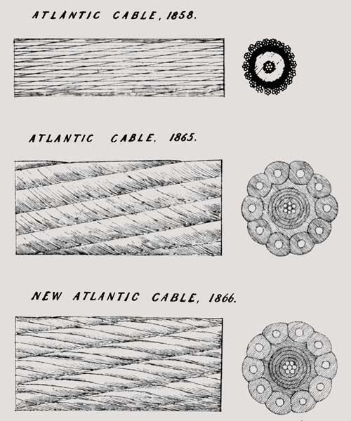 |
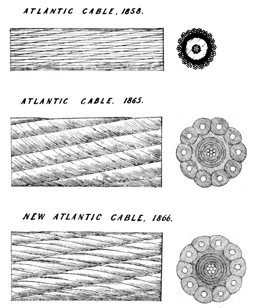
First Atlantic.—Length as laid, 2022 knots; copper conductor 7-wire strand, weighing 107 lbs. per knot, diameter 0.083 in.; covered with gutta-percha, weighing 260 lbs. per knot, diameter, 0.38 in.; served with tanned hemp, and covered with eighteen strands of seven bright charcoal iron wires 0.028 in. diameter; total diameter of cable 0.62 in.; weight of cable in air per knot 21.7 cwt.; in water 16.3 cwt.
Second, or 1865 Atlantic.—Length when complete in 1866, 1896 knots; copper conductor 7-wire strand weighing 300 lbs. per knot; diameter 0.114 in.; covered with gutta-percha and Chatterton’s Compound, weighing 400 lbs. per knot, diameter 0.464 in.; served with wet tanned hemp covered with ten bright steel wires, each enclosed in five tarred manilla hemp strands, diameter of each wire 0.095 in.; diameter of strand 0.28 in.; diameter of cable 1.125 in.; weight of cable per knot in air, 35¾ cwt.; in water, 14 cwt.
Third, or 1866 Cable.—Length as laid, 1858 knots; similar to 1865 cable, except that the steel wires were galvanized and the manilla strands were not tanned but left white. Weight in air 31 cwt., in water 14¾ cwt.; breaking strain, 8 tons.
There are some popular fallacies connected with cable-laying which are exceedingly tenacious of life—one is, that inasmuch as the wires are laid round a cable like a corkscrew, they will stretch a great deal before supporting the cable, and so the core will be injured by having to support a considerable part of the strain. In point of fact, nothing of this kind occurs. The iron wires abut one against the other, and form a tube which cannot diminish in diameter as a corkscrew does, or would do, if made of soft wire; and experiment shows that an iron-covered cable stretches very little more than a simple straight iron wire. Cables of the Atlantic class stretch a little more, for the soft strands are compressible; but even in this class of cable, the elongation, with half their breaking strain, is quite insignificant, and with the strain actually used it is insensible. Then some people say these cables untwist, and they certainly do a little, but the cables recovered from great depths prove that the number of turns which are thus taken out of a cable are quite insignificant, producing no sensible elongation or change in the lay. Others think the rise and fall of the ship must cause sudden jerks and great changes in the strain on the cable as payed out, and quite a small army of patents stand ready to defend the right of inserting some elastic contrivance by which the cable is to have a certain play. Probably the see-saw which these contrivances might introduce would be far more dangerous than the evil they are designed to remedy, for in truth the strain changes very little even in heavy weather, so long as the ship is going fast enough to let the cable lie at a small angle with the horizon. When the cable hangs vertically the case is different, though even then the change of strain is much less than would be supposed. With the Great Eastern as a point d’appui the variation was hardly sensible. Another array of patents defends the privilege of laying a cable through a long auxiliary tube, or with a long auxiliary cable; four patents for this contrivance were taken out in 1857. Other gentlemen wish to tack floats on to the cable; others, parachutes; others, gum and cotton, so as to buoy the cable up for some time; then the gum or glue dissolves, and lets the cable down quietly. It is both amusing and sad to read these and many other contrivances. Surely the man who makes a bad invention, and believing it to be good, spends his life and his fortune in the vain attempt to achieve an impossible success, is almost as fit a subject for commiseration as the real inventor who fails to reap his just reward; and then the former class are much more numerous than the latter.
The machinery now in use for laying cables acts extremely well; if the cone and rings were in general use, no further improvement would be required. An experiment by Messrs. Siemens Brothers to use a reel mounted on a turn-table in the ship’s hold, and driven by a steam-engine, deserves notice, and to some extent praise, as, at any rate, an experiment out of the beaten track; but the experiment was not successful. Captain Selwyn has proposed a floating reel, the speed of which would be regulated by the floats of paddle-wheels; but contractors who have achieved success by the old plans will be slow to tempt fortune by trying these novel contrivances. It will be seen that very little improvement has been made in the paying-out machinery of late years, simply because it was not wanted. The cone and rings date from 1855; the Appold’s break from 1858; water-tight tanks were first made in 1858 for the Red Sea Cable, but first used by Messrs. Gisborne and Forde for the Malta-Alexandria Cable in 1861. Since then, no material change has been made in the arrangements.
It is far otherwise with the electrical tests during submersion.
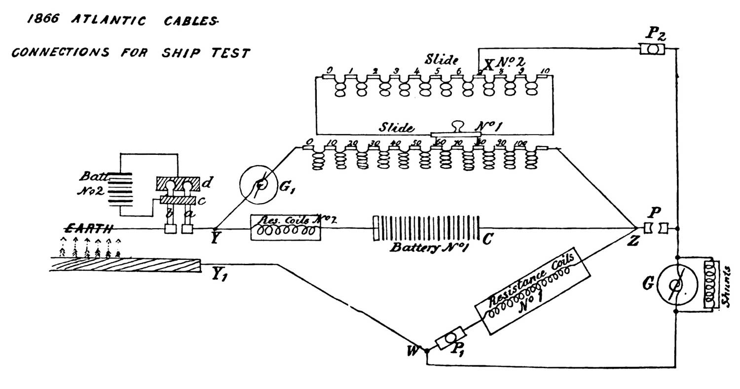
The object of tests during submersion is twofold: first, to detect instantly any injury which may occur; and, secondly, to ascertain the position and nature of the injury. Time is of extreme importance in these tests. Faults on board almost always are caused at or near that part of the cable which is in the act of leaving the ship. That is the only portion which is being disturbed, and it is hardly possible that a change can take place elsewhere. If the fault be instantly detected, the ship stopped and the cable arrested as speedily as is consistent with safety, the fault may be retained on shipboard, or if it pass into the sea, only a short length of cable will have to be hauled back before the faulty portion is recovered. As soon as it is quite certain that a fault exists, and the necessary steps have been taken to prevent the cable from running uselessly into the sea, means must be adopted to ascertain where the fault is. One rough method is to cut the cable in the hold near the part being payed out, and then by examining successively the portions in the ship and in the sea, to determine whether the fault is still on board; but electrical methods exist by which, before or after the adoption of this simple examination, the position of the fault can generally be fixed with considerable accuracy. Few statements concerning telegraphy excite more surprise than this does; few people know that accurate measurement of electrical phenomena is possible; some even think that electricity is an agent almost capricious in its action; but those who have learnt that the electrical properties of a conductor or an insulator are susceptible of definite numerical expression, should feel no surprise on hearing that when the electrical properties of a submarine cable of uniform construction are observed to undergo a definite change in virtue of some alteration at some one point, it is quite possible to make such a series of measurements as shall fix the position of that point. There are only two unknown quantities, and whenever by experiment equations can be obtained, including these unknown quantities, they can be determined. Quitting generalities, let us try to show how this is done. We will first suppose that the simple insulation test has shown that the conductor is no longer fully insulated.
A measurement must be made of the resistance of the conductor intervening between the ship and the sea at the fault or earth, as, oddly enough, it is always technically called. If this measurement give 40 units, and the resistance of each knot of the cable is already known to be 4 units, the observer will know that the fault cannot be more than ten miles off. It has already been stated that the electrical resistance of a wire or conductor can be measured with extreme accuracy, and that, as the resistance is proportional to the length, the length in circuit can be calculated from the resistance. Still, from our one measurement, we have not got information enough to know certainly where the fault is,—we only know that it cannot be more than ten miles off; it may be less, for the fault itself may have a certain resistance, and about the fault we as yet know nothing. But suppose we can now obtain a similar measurement from the other end of the cable, and this gives 600 units, while the whole length of the cable is 150 miles, we shall then know that the fault is five miles from our end, and has a resistance equal to 20 units; the resistance as measured from our end consists of five miles of conductor and the fault, or 40 units in all, that from the other end consists of 145 miles of cable and the same fault, or 600 units in all, and no other position or resistance of the fault will agree with the two observations made. A comparison with a pipe of water may make this clearer to non-scientific readers. Let us take a pipe 150 yards long, and suppose that we know exactly how much water will run through any given length of a pipe of that diameter from given cisterns at each end. Now, suppose a leak to occur in that pipe: if we stop up the far end, and let the water run in from our cistern, we find that as much water runs out as would be allowed to pass by a pipe ten yards long, we then stop up our end of the pipe and let water run in from the far cistern. We find as much water is conveyed away as would be allowed to pass by a pipe 150 yards long; then, as in the electrical case, the leak in the pipe must clearly be five yards from our end, and it must have a resistance equal to that of five yards of pipe. Thus the position of a leak in a water-pipe might be discovered, although the leak itself were buried in the ground. The electrical experiment is quite analogous to this, and is in practice made much more easily than the experiment with water-pipes could be made, for the laws of the flow of water in pipes are much less well understood, and less simple than the laws of the flow of electricity, although we may think we know better what water is than what electricity is.
In cables containing more than one wire, the above test, or something analogous to it, can always be made, for the faulty and good wire being joined together at the distant station, can be treated as one conductor, of which the observer has two ends in his possession. He can then arrange his test so that his observations at both ends are really simultaneous with the fault in the same condition when added to the two circuits. In this case, a test based on the above principle is quite perfect, and will fix the position of a fault with great nicety. But where the cable has only one conductor, the two tests must be made by different observers at different times. Faults have a disagreeable art of varying very rapidly, so that their resistance is never the same for two minutes or fractions of a minute, and then the test becomes inaccurate, though not actually useless. For instance, the observer in the first case might feel quite sure that the fault was not more than ten miles off, even if he got no information from the other end; if the fault were caused by a nail joining the copper and iron of the cable, it would have no sensible resistance, and the above test would show it was exactly ten miles off. Even if the cable were broken, the observer could guess from the variation of the fault, the current it returned, and other peculiarities, whether it was likely that the fault had much resistance, and thus form by the aid of experience a fair guess at its exact position.
The measurement of resistance is far from being the only test of which the results can be expressed with numerical accuracy; for instance, the statical tension at any point of the wire, its potential, as it is called, can be measured by electrometers, and indirectly by various methods. This statical tension is the quality, in virtue of which one electrified body attracts or repels another more or less strongly. When a current is flowing from a battery through a conductor to earth, the potential gradually decreases from a maximum at the battery to zero at the earth, and decreases according to well-known laws. The observation of this potential at any point gives additional information, therefore, by which the condition of the conductors may be determined. To revert to the analogy of the water-pipe, the potential would be represented by the pressure per square inch, or head, inside the pipe at each point; it would be greatest near the cistern, and gradually decrease to nothing at the mouth of the pipe where the water was discharged.
Another class of fault is more easy to manage. If by accident the pipe got choked up instead of having a hole in it, nothing would be easier than to tell where the obstruction lay, by measuring the quantity of water we could pour into the pipe before filling it. Then knowing the capacity per unit of length, we could calculate the distance by simple division. Exactly so the capacity per unit of length of an electric cable for electricity can be, and is measured, so that if the conductor is broken inside the insulating sheath, without a fault of insulation occurring, the distance of such a fault can be obtained by a simple measurement of the charge which the insulated conductor will take. In short, we can measure current, resistance, potential, and quantity. What is to be measured depends on the nature of the fault observed; but from these measurements, or some of them, wherever they can be made simultaneously at each end, the position of the fault can be fixed. Unfortunately, no system of tests on one side of a fault can give its position. A bad fault far off, and a small fault close at hand, cause all the elements which can be observed to vary simultaneously, so as to give no clue as to which has occurred. A bad fault, or one with little resistance, can have its position fixed on the assumption that it has no resistance; but a slight fault absolutely requires the distant test before its position can, even approximately, be determined. Fortunately, signals from the distant end can always be sent past such a fault. We are now in a position to consider the tests hitherto used during laying, and the improvements used on the Atlantic expedition.
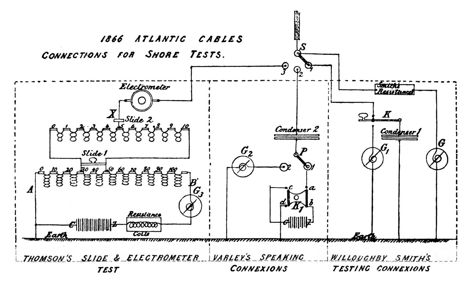
In very early days people were satisfied if they could speak through a cable whilst it was being laid. Then came the simple insulation test at definite times. Then more complex tests, spaced off into five minutes of this, ten minutes of that, and six minutes of the other, so that each hour was cut up into complex fractions, during which the ship and shore had simultaneously to make more or less complicated changes. If a fault was detected during one arrangement, perhaps half an hour would elapse before the time for speaking and either sending or receiving intelligence would come round. Or, worse still, a fault might occur and not be detected because the connexions at the time were arranged for speaking, or for a mere test of continuity, etc. Then blunders would arise from time not being perfectly kept, or from some of the many changes having been incorrectly performed, so that probably this plan was practically inferior to a simple insulation test permanently maintained. It was, moreover, rigid, and could not be readily altered to suit the special tests required when a fault did occur. All these defects were remedied for the first time during the Atlantic expedition of this year. The end of the cable at Valentia was not quite insulated; it was connected with the earth through an enormous resistance, so great that the insulation test of the cable was hardly sensibly affected by the small leakage through it; but this small leakage was easily perceived by an astatic Thomson’s reflecting galvanometer. When, therefore, an insulation test was being made on board the Great Eastern, the current used was perceived at Valentia, where the observer could further judge of the tension or potential produced by the Great Eastern’s battery by observing the current it would produce through his enormous, but known resistance. Any fault would lower that potential, and reduce this current at Valentia. More than this, the Great Eastern, by slightly decreasing or increasing their battery, could cause such small changes in the current observed at Valentia as should serve as signals, and this without intermitting their insulation test. Conversely, Valentia, by drawing off little charges, or adding them, could produce effects similar to slight changes in the insulation of the cable, and those effects could be used as signals from the shore to the Great Eastern; being of short duration, and definitely arranged, they could not be mistaken for faults. Thus simultaneous and continuous tests could be made on ship and on shore. Nevertheless, conversation could be carried on in either direction, at any time. No fault of insulation would escape detection, even during conversation, and as soon as it did occur the instruments were ready arranged to make those simultaneous tests by which alone its position could be determined, and then to transmit that intelligence from one end to the other. The merit of this admirable invention is due to Mr. Willoughby Smith. The details of the arrangement actually adopted were written out by him, in concert with Sir W. Thomson and Mr. Cromwell F. Varley, whose valuable assistance had been given to the Atlantic Company from the time of the failure of the 1858 cable.
The above description of Mr. Smith’s invention is not strictly accurate as applied to the arrangements used during the expedition, but the leading idea remained unaltered. Thus the Wheatstone balance was used to measure the insulation resistance in definite units, instead of the simple deflection insulation test. The bridge was arranged with what Sir William Thomson calls a potential divider, a set of resistance coils giving 10,000 equal subdivisions by the mere sliding of two contact pieces. Continuity is never lost, nor the resistance changed, in these slides,—a considerable practical advantage. A special galvanometer was introduced to test continually the constancy of the ship’s battery, without which constancy the potential tests would have been much diminished in value. On shore the potential produced by the ship’s battery was measured by two methods perhaps more accurate than the deflection, through Mr. Smith’s galvanometer and large resistance. One method, also suggested by Mr. Smith, was by discharges taken from a condenser charged by the conductor of the cable; the second by an electrometer reading, which could compare the potential of the cable with that of each of the 10,000 subdivisions of a slide similar to that used on shipboard. The battery producing the current through coils of the slide was on shore also maintained constant, or corrected by observations on a special galvanometer. By these arrangements the observer could obtain, in a simple form, the various elements required for the immediate calculation of the distance of a fault, had one occurred.
The speaking arrangements were also modified. Charges were not actually withdrawn from the cable, or put in at the shore. The withdrawal of a succession of charges would have produced an appearance alarmingly like a fault. Mr. Varley suggested the use of a condenser attached to the cable on shore by which he induced slight positive or negative charges, which transmitted the signals to the Great Eastern. He, as it were, instead of at each signal withdrawing a few drops of fluid from our typical pipe, pushed the water a little way back in it, or pulled it a little way out, and signalled by these impulses without withdrawing one drop of the fluid. When messages were being received on board the Great Eastern, they simply caused the slight necessary oscillations in the marine galvanometer (an invention of Sir William Thomson’s, dating June, 1857), which were insufficient to disturb the insulation test. When the signals were being sent from the Great Eastern, the rush of current in and out of the cable would have disturbed the galvanometer unduly, so it was shunted; that is to say, a part of the current was derived by a little sliding arrangement,—at the end of each word the slide was moved, and a perfect insulation test made. These various practical improvements can only be understood by professional men, but the leading idea of Mr. Willoughby Smith’s plan may be grasped by all. The arrangements worked as well in practice as they were admirable in theory. Fortunately no fault occurred.
When a fault does occur, stopping the cable is a very trying and hazardous proceeding. It can only be done gradually. The ship is perhaps running at six miles per hour, or a mile in ten minutes. She will not lose her impetus for a considerable time, even if the engines are reversed; and when the ship is stopped, the cable cannot be instantly checked,—if it were, the strain would rapidly become far too great for it to bear. The twelve or fifteen miles which lay straight on the inclined water-plane, as before described, would quickly fall into the common catenary curve, of which the whole weight would have to be borne ultimately by the cable at the ship’s stern; for when the cable ceases to sink, the resistance of the water ceases to buoy it up. The strain caused by a flat catenary of this length is enormous; thus, if in a depth of two miles only ten horizontal miles intervened between the ship’s stern and the point where the cable lay on the ground, the strain due to the catenary would, with the Atlantic Cable, be fourteen tons. In practice, therefore, the cable is generally restrained by such a force as is thought safe, and then allowed to run out until it lies in a catenary short enough to produce only this small strain, or if the cable must be held, the ship must go astern over the cable. When the foul flakes occurred during the 1866 Atlantic expedition, the Great Eastern was stopped in two minutes after the signal was given, and only 130 fathoms of cable payed out during that time. The only time which can be safely saved is the time between the occurrence of the fault and the alarm; and, secondly, between the detection of the fault and the decision of the electrician as to its probable nature and position. The arrangements of 1866, in both these respects, were greatly in advance of all that had been previously attempted.
By far the most remarkable recent achievement in submarine engineering was the recovery of the 1865 Atlantic Cable from a depth of two miles. Cables obviously could be laid in deep as in shallow water—this was a mere question of mechanical arrangement,—but very few persons possessed an imagination sufficiently hardy to allow them even to conceive the possibility of recovering a rope which had sunk to the bottom of the Atlantic Ocean. It is not true, as is now frequently asserted, that no one but those engaged in the expedition had any hope of success; for so soon as it appeared from the attempts made in 1865 that the cable could be hooked, Mr. Henley, Mr. Fleeming Jenkin, and a little later Mr. Latimer Clark, publicly expressed their conviction of the probable success of the undertaking; but it is certain that the public, and some even of the directors of the companies concerned, entirely disbelieved in the possibility of success, and put no faith in the assurances given, that the cable really had been found in 1865. Success had attended similar attempts in considerable depths—this was known to engineers,—and calculation showed that what had been done in 600 fathoms by Mr. Henley was possible in 2000 fathoms. Still the greatest credit must be given to Mr. Canning, now Sir Samuel Canning, for his courage in making the attempt in 1865. Few men would have had the nerve to begin an apparently hopeless search at the very moment of failure in a great but comparatively simple undertaking. The admiration is due not so much to the means adopted either then or in 1866—they were simple enough,—but to the resolution which prompted the attempt at a moment of great depression. The result will have, or ought to have, a greater effect in promoting the establishment of deep-sea cables than the successful submersion of a dozen cables across the Atlantic. It had been thought and said that men sharing the risk of a deep-sea cable were embarked in a desperate or gambling venture; one accident, and their money was irretrievably lost. This view had been especially advocated by Mr. Francis Gisborne with great show of truth. He contended, and many approved of his opinions, that it was madness to venture across a deep sea, when a cable could be laid in shallow water, simply because in shallow water the cable could always be repaired, whereas in deep water they could not, and one fault involved the loss of the whole capital embarked. This argument, if not entirely swept away, is very much weakened. Deep-sea cables are no longer gambling ventures, but legitimate speculations.
Nothing can be simpler than the means by which the result was attained. A grapnel or small anchor with five prongs, hung to the end of a hemp and steel rope two and a half miles long, was slowly dragged along the bottom of the sea across the line where the cable was supposed to be. The strain on the steel rope was watched; sometimes it rose, and sometimes it fell, as the ship went a little quicker or slower through the water, or as the prongs bit more or less deeply into the sand.
Presently the strain rose from 42 cwt. to 80 cwt., and this strain did not again decrease; but, had the ship been allowed to drift further, would have continued to increase. Surely this increase of strain was due to the cable as it lay on the bottom. The ship’s head was allowed to come round so as to face the supposed cable; the steel rope was hauled in; the ship brought vertically over this rope. Still the strain increased, instead of decreasing, even when the length of rope still out of the ship could not reach to the bottom, and then those on board knew that the cable hung on the grapnel. If the cable were not there, the strain would decrease as the weight of steel rope hanging to the bow decreased, but an increase of strain surely proved that more and more weight was being lifted as the grapnel approached the ship, and what conceivable object could produce this effect except the cable, of which a greater and greater length was every minute being lifted from the bottom? This was the reasoning which, in 1865, proved to all on board that really on more than one occasion the cable had hung upon the grapnel. It is needless to say much of the failure to bring the cable to the surface —a failure caused by weak shackles and insufficient machinery,—but it is quite worth while to attend to the reasoning of many persons who, in 1865, wrote to prove that, even if the cable were found again, it could not possibly be brought to the surface by mere hauling. The argument used was, that such an enormous length of cable must be lifted, stretching east and west on either side of the grapnel, that it would break under its own weight long before coming to the surface,—as one gentleman put it, there was not a sufficient length of cable to reach to the surface. This argument had a certain amount of truth in it, but those who urged it did not generally take the trouble to make accurate calculations, and some made erroneous calculations. Stretch a piece of fine chain, 100 inches long, across a floor, lay it straight, and fasten down the ends; try to raise it in the middle, and you will find that, unless it has been pulled very taut indeed, it will rise an inch or two without difficulty. Even when a cable is supposed to be laid taut, it can be raised to a surprising distance; but the 1865 Atlantic Cable was not so laid; it contained 12 per cent. of slack cable; that is to say, 112 miles of cable lay on about 100 miles of ground. Now, lay the 112 inches of chain on 100 inches of floor and fasten the ends as before. The middle of the chain can now easily be raised 21½ inches from the ground. The chain will then hang on each side of the point of suspension in catenary curves; the weight supported by the string used to lift the chain will simply be the weight of the chain that is off the ground; the strain on the cable at the point of suspension will be equal to 83½ inches of chain. This strain is less than the whole weight of the cable lifted, so long as the angle made by the chain at the grapnel is less than 120 degrees, as will always be the case when more than 6 per cent. of slack exists; it is a minimum, and equal to half the weight lifted when the cable hangs vertically down on each side of the grapnel, or when the slack is infinite. The more the slack the less the strain, for less cable will be lifted before the grapnel reaches a given height, and the angle at the grapnel will also be more favourable. With 12 per cent. slack, nearly 9¾ miles must be lifted from the ground to reach to a height of two miles. The weight of Atlantic Cable so lifted would be about 6¾ tons; the strain on the cable near the grapnel less than 5½ tons. As the cable would bear 7¾ tons, it was clearly possible to lift it by mere hauling. Moreover, the strain at the bottom would in this case be four tons, tending to pull in more slack from either side, and thus diminish the whole length lifted and consequent strain. By increasing the length of our experimental chain on the floor, and omitting the fastenings at the end, which in the actual cable only exist as friction in the sand, this effect may be clearly seen, and if, instead of tying the chain to the string used to lift it, the experimenter will fish for the chain from a table with four bits of wire, bent into a fish-hook shape, with their shanks bound together, making a mimic grapnel, the illusion will be complete, and the dredger will be surprised to find with what certainty he can hook the cable on a moderately smooth carpet. In 1866 the cable was once fairly hauled to the surface by mere brute force. Calculated from the weight (6½ tons) then on the grapnel, 9¼ miles of cable must have been hanging by the rope. The catenary formed was such as to require 15 per cent. of slack. The strain at the bottom, of about 3½ tons, had therefore pulled in an extra three per cent. along the sand on either side. The strain on the cable was about 4½ tons, but with this strain, or little more, it parted shortly after being brought to the surface, and before, owing to rough water, the necessary stoppers could be fixed to it from the ship. This simply affords another instance of the very well known fact that no engineer should ever depend on obtaining, at all points, the full theoretical or experimental strength of a cable or other structure. There must be a margin. The cable was finally secured by the plan recommended almost unanimously by all who had experience in similar undertakings. Suppose the chain on the floor laid too taut to come up to the level of the table without breaking; if we with a pair of nippers cut the chain a few feet to our right, a little will slip over the grapnel, the two ends will hang down vertically, and we shall easily land our prize. Just so when the Great Eastern had hold of the cable. She directed the Medway to find it, and lift it three miles nearer to America, she then told the Medway to haul away as fast as she could to break the cable, and the Great Eastern hauled in more slowly, but fast enough to keep hold of the cable with her own grapnel. When the Medway got the cable within 400 fathoms of the surface, it broke at her grapnel. The end fell down and the loose bight was easily hauled on board by the Great Eastern. The strain on this occasion was six tons. Owing probably to the hemp covering, the cable did not slip along the grapnel after being cut by the Medway. The only chance of failure was that the cable might have rusted so much that, even when hanging vertically, it could not bear its own weight in two miles of water. On the contrary, little or no signs of rust were observed, and there is no reason to suppose that the 1865 cable had materially lost strength during its year of submersion. Considering the perfect success of this simple method of recovering the cable, it really is unnecessary to discuss the many ingenious plans suggested; probably the use of a holdfast grapnel in one ship, and a cutting grapnel in the other, would avoid a few mischances; but it is clear that even these appliances are unnecessary. A few accidents from broken chains, weak swivels, stoppers that slipped, bent grapnel-prongs, etc., did occur, and always do occur, even when cables are repaired in shallow water, and, indeed, the repairs of cables in the English or Irish Channel often last longer than the three weeks occupied in recovering the Atlantic Cable. A rocky bottom causes more difficulty and delay than two thousand fathoms of water.
The cable, when recovered, proved perfect; and, on the 2d of September, Sir Samuel Canning telegraphed to Sir Richard Glass, the able manager of the contracting company, that he had much pleasure in speaking to him through the 1865 cable. It was a noble triumph, well earned. The 1865 cable was completed on September 8, 1866. It lies about thirty miles north of the 1866 cable. Those who wish to learn more of the history of this enterprise will find accurate and clear information in The Atlantic Telegraph, by W.H. Russell, LL.D., illustrated by R. Dudley; and in the diary of Mr. Deane, the secretary of the Anglo-American Telegraph Company, published in the Times.
The success of the Atlantic Cable was not gained by the effort of a single genius, but resulted from the co-operation of many minds, and divers kinds of men. Some have followed the undertaking from first to last; for instance, Mr. Cyrus Field’s unflinching faith has carried him on from first to last as an advocate whose zeal never flagged. Sir Richard Glass was a member of the firm of Glass and Elliot, which made half of the first cable, and he is the manager of the Company which has successfully completed the task. His work is known to all who practically were connected with the undertaking. He is the recognised chief of all, and willingly recognised. Sir Samuel Canning and Mr. Clifford accompanied the first expedition. Sir Wm. Thomson was on board the Agamemnon in 1858, and has freely spent time and money in forwarding a work in which he saw a means of worthily employing the powers of a mathematician, the experimental skill of a naturalist, and the inventive faculties of a man of genius. His name has already been frequently mentioned as first to make this and that invention or improvement; and not only has he reaped with his own hand a meet harvest of scientific discovery, but he has the satisfaction of having prompted others whose work has been a supplement to his own; and indeed he may be said to have founded a new school of practical electricians in England. Mr. Varley came later into the field, but he too worked hard, and his assistance during the long period of depression from 1858 to 1865, and at Valentia during the last expedition, together with his additions to the testing and speaking instruments, give him strong claims. Mr. Willoughby Smith, of whose beautiful system of testing it is difficult to speak too highly, has only lately been placed in high command, but indirectly, as electrician to the Gutta-Percha Works, from first to last he has helped, and helped effectually, in improving the materials employed. Mr. Chatterton, the manager of those works, should not be passed by in silence. To these must be added the well-known names of Captain Sir James Anderson and Commander Moriarty, C.B., as well as those of the early pioneers, Sir Charles Bright, Mr. Whitehouse, and Mr. de Sauty, and last, not least, the Directors and Officers of the Atlantic Cable Company, the Anglo-American Company, and the Telegraphic Construction and Maintenance Company. The difficulties these gentlemen have had to contend with do not admit of being scientifically stated. They can indeed only be known within a very narrow circle, but those who have been similarly placed, and have had to administer the affairs of a company heavily involved in a dangerous undertaking, requiring continually large supplies of fresh capital, will be able to guess at the work and anxiety they must have undergone. A pair of Baronetcies among them all is really a moderate reward.
But now that the rewards are distributed, and the cables are laid, how are they being used? Alas! very little as yet. Perhaps no one even believes that a long submarine cable ever will be laid, and so preparations are never made to meet it. The Persian Gulf Cable was laid nine months before the land lines were completed which allowed it to transmit messages. Until very lately they were so wretchedly bad, or badly managed, that messages often spent a week in the overland journey, and arrived so much out of condition as to be unrecognisable by their friends.
The Atlantic Cables end at Hearts-Content, Newfoundland, and the journey of the messages often ends there too. It is said that up to the beginning of November, since the line was opened, the lines from Newfoundland to America have been interrupted for thirty days, or nearly one third of the whole time. Through large tracts of desolate country a single wire was expected to do all the work, and no due arrangement for its management seems to have been made. The short submarine line from the island to the mainland, laid in 1856, and eighty-five miles long, was out of order when the 1866 cables were completed, and so we have hitherto reaped comparatively little benefit from those cables, looked on as a commercial speculation. The high price of £20 for a twenty-word message, only recently lowered to £10, has been justified by the fact, that if many messages had been obtained from the public, they really could not have been sent. So in practice one or two hours’ work per diem has been sufficient to send on one cable all the American and European Continents had to say in a hurry. This cannot last, but it is almost amusing as a commentary on the lively disputes which occurred on the power of the cables to transmit a large amount of work. In time the outlet from Newfoundland will be completed, and the cables will then surely be flooded to such an extent as to test their utmost capabilities.
Engineers and electricians, half-alarmed at their own audacity, gave certificates that seven or eight words per minute might be sent along the new cables. New and complex instruments were devised to insure even this result, and now eighteen or twenty words per minute have been obtained; with the omission of many of these inventions, twelve words per minute is the fair average speed. Nevertheless, the engineers and electricians were not to blame. On the contrary, they deserve praise for their moderation. To explain how their estimate was formed, a sketch of the theory of the transmission of submarine signals is required, and here again Sir William Thomson must be named as the first to state that theory, and draw the main conclusions from it. In a letter to the Athenaeum, dated November 1, 1857, Sir William Thomson pointed out, in opposition to Mr. Whitehouse, then electrician to the Atlantic Telegraph Company, that the number of words which in a given time could be sent through a long submarine cable varied inversely as the square of the length of that cable; that when the length of a cable was doubled, only one quarter the number of messages per diem could be sent through it. In a paper published in the Proceedings of the Royal Society, Sir William Thomson gave the complete theory, showing that on all lines a limit existed to the speed of transmission, and giving an estimate of the probable speed through the 1858 Atlantic Cable as three words per minute.
The speed of electricity used to be given as 288,000 miles per second, but in reality Professor Wheatstone’s beautiful experiments only proved that this speed might in given circumstances be attained. Electricity seems to have no proper speed, in the usual sense of the word. The speed depends in each case on the condition of the conductor,* and may on certain conceivable conditions be treated as infinite, though we have no proof that the laws now known hold good up to or nearly up to this limit. When the Valentia end of the Atlantic Cable is joined to the signalling battery, a current rushes into the cable without any perceptible loss of time, but no effect whatever can be perceived in America for at least one-tenth of a second; after say fifteen-hundredths of a second, the received current begins rapidly to increase, according to a definite law, and if the battery contact at Valentia is continued, the current entering the cable there, and that flowing out of the cable at Valentia, will be sensibly equal after say two and a quarter seconds. After this the currents would remain equal so long as the battery remained in action. When the battery contact is broken at Valentia, and the cable put to earth, the current flows on at Newfoundland for say one-tenth of a second, as if nothing had happened; it then begins rapidly to decrease, and sensibly ends say two and a quarter seconds after the contact was broken.
*This fact, and the increased retardation observed in underground wires, and therefore in submarine cables, is guessed, or rather foreseen, in a very curious proposal for an electric telegraph, by Francis Ronalds, published in 1823, containing an account of experiments made in 1816, long before the days of Gauss or Cooke and Wheatstone, before even the discoveries of Oersted and Ampere, which have rendered our present system of telegraphy possible. The writer is indebted to Mr. Latimer Clark for the knowledge of this fact. Mr. Ronalds’ proposal, based on actual experiments through eight miles of wire, deserves to be better known than it is. His book is called Descriptions of an Electrical Telegraph, and was published for R. Hunter, 72 St. Paul’s Churchyard, in 1828.
Thus the current arrives in gradually increasing waves, and dies out in a precisely similar manner. (The numbers given are not the results of direct experiment, but are probably not far from the truth.) On an average three waves, or arrivals of waves, are required to indicate a letter of the alphabet, and five letters are required for each word, so that if on each occasion the wave had to rise to its maximum and fall to its minimum, each letter would require twelve seconds for its completion, and one word per minute only could be sent. With the ordinary Morse instruments used on land and short submarine lines, probably this result would nearly be the limit of the working speed. On the Malta-Alexandria Cable, which has a larger core, and one, therefore, better adapted for speed than the Atlantic Cable, only 3.18 words per minute were obtained through 1330 knots. Calculated from this, and allowing for the difference of the cores, the speed on the Atlantic Cables would be little more than 1⅓ words per minute; and be it remarked that until the present year no other instruments than these ordinary Morse instruments were in practical use on submarine lines. Our engineers were therefore bold when they promised seven or eight times this speed by means of new instruments. Moreover, the New Atlantic, even allowing for the difference in length and in copper, can only be about two and a half times as good a speaking instrument as the 1858 Atlantic, on which only two and a half words per minute had been obtained.
In order to produce a succession of distinct and legible signals, it is not necessary that the wave should reach its maximum and fall to its minimum at each signal. If the sending battery contacts are changed or reversed before the full height of the wave is reached, the wave is not obliterated, it is simply diminished; if battery contacts, alternately with one and the other pole of the battery, succeed one another with considerable rapidity, say three reversals every second, or ninety dot-signals per minute, the waves will be reduced to say 10 per cent. of their maximum; but if we can render these little waves visible, they may be interpreted as legible signals. The old Morse system, which simply indicated a blunt Yes or No, could not show these little waves, or follow them in any way. Sir William Thomson’s reflecting galvanometer does render these little waves legible, even when they are no larger than one per cent. of the maximum current. The received current deflects a tiny magnet to and fro. A little mirror swinging with the magnet reflects a spot of light on to a distant scale, where by its oscillations the spot of light indicates movements of the magnet too small to be directly seen. The little swinging magnet follows every change in the received current, and every wave, great or small, produces a corresponding oscillation of the spot of light on the scale. These little oscillations, produced in due order, are easily read by a practised clerk,—no one knew how easily. The sending arrangements were designed to produce perfect regularity in these little waves, making them as sharply defined as possible; but just as by a practised eye handwriting can be read in which there is no single clearly formed letter, so it has been found that a clever clerk will instinctively, as it were, disentangle most irregular oscillations of this little spot of light into the letters and words they should represent, and from this cause the greater part of the sending gear has been found unnecessary, and yet the bold estimate of eight words per minute has been exceeded. The addition of a single simple little instrument allows four times the number of words to be sent through the Atlantic that could be sent through the Malta-Alexandria Cable, of little more than two-thirds the length. Here, then, is at least as great an advance as in the other branches of submarine telegraphy. In future long cables the speed may be calculated on this new basis, which has long been advocated by a few, but which had not received practical confirmation till now. The speed at which messages can be sent through a given length of cable is simply proportional to the quantity of copper and gutta-percha used, provided the relative proportions of these materials remain unchanged, as is now practically true in most cases. The new experiment would therefore allow the engineer to adopt a core of one-eighth the weight which he could have adopted upon the old system of telegraphy to obtain the same speed; or if he be not bold enough to adopt so small a core as this would sometimes lead to, he may at least choose the smallest core which on mechanical grounds he thinks safe to adopt. Here we may catch a glimpse of possible cheap cables hereafter.
So long as the cable was coiled on board the Great Eastern, it was not possible to transmit more than five or six words per minute through it, even with the best appliances. The difference between a coiled cable and a straight one, as a means of signalling has long been known, and that difference appeared from Mr. Jenkin’s experiments on the Red Sea Cable (Transactions of the Royal Society, 1862) to be possibly great enough to halve the speed, or even reduce it to a still smaller fraction of that obtained on the straight cable; but crucial experiments on this point were wanting. The extra retardation is produced partly by the induction of the current on various parts of itself in neighbouring coils, and partly by the magnetization and demagnetization of the iron sheathing, which forms a sort of huge electro-magnet. The effect produced by the coiling is analogous to giving the electric fluid an inertia, and consequent momentum, an analogy long since pointed out by Sir William Thomson, in a paper by him and Mr. Jenkin on the discharge from a coiled cable, published in Phil. Mag., 1861. A new illustration of this analogy was discovered on board the Great Eastern by Sir William Thomson, in the fact of an oscillating current flowing in and out of the insulated cable when first charged. This phenomenon was described by Mr. Varley in a paper read at the meeting of the British Association this year at Nottingham, and published in the Athenaeum of the 15th September.
The signalling arrangements on board ship and on shore present this peculiarity, that there is no voltaic circuit. The current is received at Valentia in a Leyden jar or condenser, which acts as a sort of elastic reservoir. When receiving, it is alternately charged by the cable, and discharged back into the cable; while the galvanometer placed between the condenser and the cable indicates the alternate forward and backward tide in the current. Similarly when Valentia wishes to send signals, it charges the condenser positively or negatively by induction from the battery, and thus causes corresponding movements in the charge of the cable. This arrangement, already alluded to in the testing arrangements, is due, we believe, to Mr. Varley, and prevents to a great extent the action of earth-currents, which would otherwise be found troublesome with so sensitive a receiving instrument as the mirror galvanometer. Much has been said concerning these earth-currents, and some people thought they would render signalling across the Atlantic impossible.
Different parts of the earth and sea are found to be at different electric potentials. One part is electro-positive or electro-negative to another. There is, that is to say, the same difference between two parts of the earth that exists between the two poles of a battery. If, then, these two points are joined by a wire, a current will flow through that wire as if from a battery, and this current is termed an earth-current, to distinguish it from a current produced by an ordinary voltaic battery. This difference of potential between two given spots, such as Newfoundland and Valentia, is not constant, but continually varies. So does the current it produces. The current, and the variations in the current, interfere with the signalling current, disturbing the distinctness of the signals. When no voltaic circuit exists, no direct current will flow from one end of the cable to the other, except that caused by the discharges into and out of the condenser; but a change in the potential of either station will still have some disturbing effect by changing the charge in the condenser. When very rapid changes take place in the electric condition of the centre, a magnetic storm is said to be taking place, and this, on all lines, will occasionally put a stop to signalling. Very little is yet known as to the cause of earth-currents or their laws. The electromotive force producing them does not seem to increase with the distance between the two ends of the line after the first few miles. No greater force than that due to ten ordinary Daniell’s cells is reported by Sir W. Thomson and Mr. Varley to have been observed at any time between the two ends of the cable. Much the same may be said of the Malta-Alexandria Cable; but Mr. Varley has spoken of a force equal to 400 cells on short land lines in England. Thus submarine lines appear to have in this respect an advantage over air lines. The latter are further subject to induction from changes in the atmosphere, producing effects similar to earth-currents. The conducting mass of the sea should screen submarine circuits from all these effects; but Mr. Varley has informed the-writer that currents were observed from the Atlantic which seemed to be of this nature. One most singular phenomenon was also communicated to the writer by Sir W. Thomson and Mr. Varley. Owing to changes in the potential of the sea, the capacity of the cable for a statical charge varied. The immense Leyden jar formed by the cable at times therefore poured out a current at one end, while the other was insulated, giving apparently more than infinitely good insulation. Not only did the battery used to test insulation then fail to force any current through the gutta-percha of the insulated cable, but a current was actually forced back on the battery, as if coming through the gutta-percha into the cable. From this cause, even if the Atlantic Cables were joined in a metallic circuit, continual currents would fluctuate to and fro between them, owing to changes in the difference of potential of the sea in their respective tracks, thirty miles apart. The two cables afford an unrivalled opportunity of studying earth-currents, about which really little is known; and it is to be hoped the opportunity will not be neglected. There is not the slightest reason to fear that they will prove any obstacle to the transmission of messages through any submarine cable, of whatever length it may be. One method of avoiding all disturbance from earth-currents is to use so powerful a battery as to overpower their effects; but this plan is not to be recommended, since the action of a powerful battery has been known to change small faults into great ones, and though not even a small fault is believed to exist in either Atlantic Cable, it is well to avoid so powerful a decomposing agent as is furnished by a large voltaic battery. 400 cells were used in 1858. For the signals sent in 1866, 12 cells are sufficient, but 20 or 30 is the number in daily use. Mr. Latimer Clark sent signals through the two cables joined in one, being a circuit of 3754 geographical miles, with one small cell formed in a thimble. In connexion with the subject of signalling, it is interesting to remark that perhaps Sir William Thomson’s connexion with the Atlantic Telegraph Cables was due to a controversy between him and Mr. Whitehouse on the subject of signalling; the letters are published in the Athenaeum from August to November 1856, and are extremely curious. Mr. Whitehouse misinterpreted some careful experiments, and remarks in one place that to lay such a cable as he thought Sir William Thomson’s theory demanded, would require Mr. Scott Russell’s Leviathan. It is needless to add that subsequent experiment has confirmed every part of Sir. W. Thomson’s theory, although the constants he used have been somewhat modified by experience.
Attention has so far been chiefly directed to the Atlantic Cables, because in connexion with these almost every late improvement has been adopted or invented. Lines in shallow water remain much what they were in general construction ten years since. Those of later design are heavier on the average than the earlier cables, for experience has shown that a saving of weight and strength results in great ultimate loss. The average life of a shallow water cable, weighing less than two tons per mile, is about five years, whereas no limit can as yet be assigned to the life of cables weighing eight or ten tons to the mile. The iron wires are now almost always galvanized, and frequently covered with hemp, and Bright and Clark’s silicated bituminous compound, which seems very efficiently to protect the cables from rust, and to prevent broken wires, during submersion, from fouling any part of the machinery, a frequent occurrence some years since, producing what was called a brush, formed by the one broken wire remaining on board in a constantly increasing coil or tangle round the axis of the rope, while the rest of the cable went overboard. The Persian Gulf Cable made by Mr. Henley, and tested and laid by Messrs. Bright and Clark for the Indian Government, under the superintendence of Colonel Stewart, was thus covered. The excellence of this cable, 1176 miles long, laid near Kurrachee, in a sea with the temperature at the bottom of 24.2°C, and at the top of 26°C. is a proof that gutta-percha may, with due precaution, be used in tropical climates.
The gutta-percha resistance per mile of this cable varies from 575 to 268 millions of British Association units per mile, according to the temperature of the bottom of the various sections. It was laid from sailing vessels towed by a steamer. The diameter of the main cable, covered with compound, is 1⅛ inches, and its weight about 3.7 tons per mile. The Lowestoft-Norderney Cable, 240 miles long, laid in September last, from England to what was Hanover, is the heaviest, on the whole, yet laid. It weighs 10½ tons per mile, is 2 inches in diameter, contains four insulated conductors, is covered with Bright and Clark’s Compound, and would bear a strain of twenty tons. It has 20 miles of shore end, each mile of which weighs 20 tons, and would bear a strain of 40 tons. The insulation resistance of each mile, as it lies in the North Sea, is 1100 millions of British Association units, and the four wires are remarkably uniform. This cable was laid for Messrs. Reuter’s Telegram Company, under the superintendence of Messrs. Forde and Fleeming Jenkin. The contract was let to the Telegraph Construction Company, and the cable made and laid by Mr. Henley. The England-Holland Cables are shorter examples of equally colossal proportions. There are now seven cables at work between England and the Continent, and three between England and Ireland. The Malta-Alexandria Cable, 1330 miles long, laid for Government in 1861, under Mr. Forde’s superintendence, by Messrs. Glass, Elliot, and Co., also deserves mention. Although not designed for shallow water it has done good service; but the frequent interruptions which occur will serve as a warning not again to use a cable weighing less than two tons per mile in shallow seas. Those who wish for fuller information concerning the less important lines, may consult the references given in the course of this article. The most important fact to be stated about shallow sea lines, is that the Dover-Calais Cable, laid sixteen years ago, is still working, and likely to continue to work for years to come.
It is extremely difficult to obtain accurate statistics as to the number of miles of cables laid, lost, and now at work. Many are in the hands of distant Governments, who give no information; and some are so frequently under repair, that it is difficult to know in what category to place them. In 1862, in Mr. Jenkin’s report to the Jurors of the Great Exhibition, 5345 statute miles of cable, and 9456 miles of gutta-percha wire, were said to be in working order; 9406 miles of cable were classed as having been successful for some time, but not then working; 557 miles were classed as total failures. These numbers were avowedly mere approximations.
Mr. Francis Gisborne published statistics in 1865, in which he put the numbers for working and now-working cables at 5066 and 11,261 statute miles respectively. Dr. Russell gave 6842, and 9407, as the length of cables at work and abandoned. Since then 3754 miles have been added to the successful list by the Atlantic expedition. The Gutta-percha Company claim now to have supplied insulated case for 12,100 miles of cable, which are still at work. Whatever the actual numbers are, it is incontestable that a large proportion of lines laid have failed from time to time. The Red Sea, and Batavia-Singapore Cables, upwards of 4000 statute miles long, failed from their want of weight and strength; they rusted rapidly, and could not be repaired when faults appeared, or when they chafed through; or rather the expense of the continual repairs was such that they were abandoned, perhaps somewhat prematurely. The failures of some deep-sea cables have in all probability been due to lightning. An unaccountable apathy has in many cases led to the neglect or actual removal of the lightning dischargers attached to submarine lines, and the writer has seen neglected dischargers with points fused and burnt away, proving that the line had been struck repeatedly. Other failures have been attributed to the tautness of the cable when laid, to friction at the bottom, to volcanic action, etc.; but not much is known about these causes, which are rather hypothetical than proved. Neglected faults have certainly, in some cases, been much enlarged, by the use of more and more powerful batteries, added by ignorant clerks.
These failures need alarm no one; they simply prove, what should be known without proof, that there is a real difference between ignorance and knowledge, between care and neglect; and that supervision after submersion is not less necessary than during manufacture. The main object of this article has been to show that the success obtained in late years, as compared with early failures, is due to no chance, but to a real advance in every branch of Submarine Telegraphy. If the reader does not understand or believe in this advance, the writer has failed in his object. He prefers to think that he has shown good reason for believing that the success is likely to be permanent. Much might be written on the proposals for still further improvements, real and imaginary. Mr. Hooper has succeeded in preparing india-rubber, so as to be apparently permanent, while it certainly surpasses gutta-percha in all the electrical properties which are required for the insulation of cables. The Indian Government has taken the initiative in employing this material, which is eminently suited for tropical climates. The other preparations of india-rubber have very generally been found subject to decay; and various newly proposed materials, such as parkesine and balata, can hardly be said to have been fairly brought before the public.
Messrs. Siemens have employed for some portion of their lines lately laid with success in the Mediterranean, a very novel form of cable, formed of hemp bound with strips of copper, which they believe will be much more permanent than the old-fashioned cables. The forms proposed, but not yet tested, are very numerous, and little is known of their merits. The cost of an experiment is so great that engineers hesitate to recommend even what they believe to be well worth a trial. It is certain that the old forms answer well, but it is equally certain that their expense will preclude their adoption, except on the main lines. A cheap light cable, durable in deep water, would lead to an immense extension of the telegraphic system. It is by no means certain that a simple gutta-percha-covered wire would not answer as well as the most elaborate cable. However this may be, the next advance must be towards cheapness;—efficiency is attained.
The importance of telegraphic communication is often claimed on very narrow grounds. The advantages in war and diplomacy are to some extent counterbalanced by very obvious disadvantages. Even the gain to individual merchants admits of doubt By diminishing risks, telegraphy is sometimes thought to diminish profits. The mere convenience of sending a message quickly is outweighed in many minds by the annoyance of receiving, at all odd hours, scraps of news, often unintelligible from their conciseness. But on the broad ground that with the assistance of the telegraph the wants of one country can be supplied from the excess of another, in little more than half the time required for the purpose without the telegraph, we may claim for that invention a recognition that it is useful, in the sense that free trade, good roads, or fleet ships are useful. The measure of that good is a problem in political economy which it is not now our business to solve; it is certainly out of all proportion with the price paid for the information sent. Up to the present time, full advantage has not been taken of the power we possess. From a want of organization and some political difficulties, we cannot at this moment send a message to any distant part of the world with a certainty that it will be delivered without considerable delay and probable mutilation. Mr. Reuter, to whom we owe the organization of the despatch of public news, has begun to organize a system by which, in time, the great capitals of Europe may really be placed in instantaneous communication. A Parliamentary Committee has been considering proposals of a similar kind extended to the East; but, meanwhile, a message sent through the Atlantic Cable may be delayed five or six days in the wilds of Nova Scotia, and mutilated messages continue to arrive after a fortnight’s journey from India. So long as this is the case, no calculation can be made of the employment which would be found for our great submarine cables if worthily worked, but the fact that much remains to do, even after the Atlantic Cable has been laid, need not prevent a just pride in a really great victory, achieved, not by chance, but by a knowledge resulting from the patient efforts of many minds for many years.
ADDENDA.
Explanation of Diagram of Shore Tests—Atlantic Expedition.
S is a switch by which the cable can be connected at pleasure with the studs 1, 2, and 3.
The cable is always connected with Smith’s resistance, through which a feeble current passes, deflecting galvanometer G, and showing by its magnitude the state of insulation of cable, or more strictly speaking, the potential at S.
When S is connected with stud 1, as drawn, Condenser 1 is charged by the cable. It can be discharged through galvanometer G1. This discharge is a second test of the potential at S. It will cause an onward movement in the current applied by the ship’s battery, and a consequent momentary change of deflection in the ship’s galvanometer. This will be a continuity test for the ship, proving the copper unbroken. This test might have been used as an arrangement for speaking from shore to ship. Two condensers of different sizes would have given two signals, from which an alphabet could be formed.
When S is connected to 2 and the second switch P to 1, as drawn, the cable will charge one plate of Condenser 2, and conversely; if the potential of the other plate be changed by being connected through the reversing key K,, alternately with each pole of the battery C Z, this will induce alternate positive and negative charges in the cable, which, being superadded or withdrawn from the original charge produced by the ship’s battery, will cause alternately backward and forward currents which will show as signals on the ship’s galvanometer. Similarly, if switch P connect the second plate of condenser to the galvanometer G2, any changes of potential in the first plate of Condenser 2 caused by the ship’s battery will induce corresponding changes in the charge of the second plate, and therefore currents to and fro through galvanometer G2, which currents may be used as signals.
The cable at S may be connected through stud 3 with the electrometer, and its potential directly measured by comparison with the potential of some point of a set of slide resistance coils, through which a current is flowing from the battery. This current is maintained constant by reducing the resistance in resistance coils, so as to maintain a constant deflection in the galvanometer G3. The potential at the successive studs of the slide 1 may be called in an arbitrary unit, 10, 20, 30, . . . . 100; and if the electrometer were directly connected with these studs, it would show with an accuracy of ten parts in a hundred what was the potential of the cable in the same arbitrary unit. To obtain further subdivisions, a second set of resistance coils, each equal to one-fifth of each of those of the first slide, are joined so as to bridge over any two of the first set. The first set, consisting of eleven equal coils, the total resistance between. A and B will always be ten units, and the ten studs of slide 2 will subdivide into ten equal parts,—the potential between the two studs of slide 1 which they bridge. Thus, as drawn, calling the total potential of A zero, and of B 100, the potential of X will be 35. Slides 1 and 2 during the test are moved till the potential is found, which is exactly equal to that of the cable. In reality, there were 101 equal coils in slide 1, and 100 in the second slide, each equal to 1/50th part of those in the first. Thus the potential between A and B could be subdivided into 10,000 equal parts.
Explanation of Diagram of Tests on board Ship.
The diagram, when connexion is made by plugs at P2, and P1, but broken at P, represents a Wheatstone’s balance, the four arms of which are, 1st, a set of resistance coils No. 1 between Z and W; 2d, part of the slide resistance coils between X and Z; 3d, the remainder of the slide resistance coils between X and Y; and 4th, the gutta-percha sheath of the cable between the conductor Y1 and the earth Y. G is the galvanometer of the balance, arranged with shunts to diminish its sensitiveness when required. The resistance of the gutta-percha = resistance coils No. 1 multiplied by XY/ZZ, or if we call S the slide reading, which, as shown, would be 67, we have S P resistance = resistance coils No. 1 x (100/67 - 1).
In the actual slides with 100 coils each, the resistance in coils No. 1 was multiplied by 10,000, divided by the slide reading, and a unit subtracted. The same formula gives the copper resistance if the remote end of the copper conductor is put to earth. Resistance coils No. 2, and galvanometer G1, were used to maintain a constant current through the slides as described for the shore tests. Y was usually connected to earth by the bar C which joins a and b, but when the keys a or b were depressed, they sent signals to the shore from battery No. 2, but these signals only slightly raised or lowered the potential of the cable, and did not much disturb the electrification. When signals were being sent, the sensibility of the galvanometer G was diminished by shunts, which were removed during the pause after each word to take a perfect insulation test. If anything had gone wrong with the Wheatstone balance arrangement, the plugs P2 and P1 would have been withdrawn, and connexion made at P, which would have established the old direct simple insulation test from C to Z, P, G, W, and Y1.
LIST OF CABLES
In Working Order.
1. Dover and Calais.
2. Denmark, across the Belt.
3. Dover and Ostend.
4. Portpatrick and Donaghadee.
5. Portpatrick and Whithead.
6. Sweden and Denmark.
7. Corsica and Sardinia.
8. Newfoundland and Cape Breton.
9. Prince Edward’s Island and New Brunswick.
10. Ceylon and India (Mainland).
11. Italy and Sicily.
12. England to Holland (Hague).
13. South Australia and King’s Island.
14. Sweden and Gothland.
15. Folkestone and Boulogne.
16. Malta and Sicily.
17. Barcelona and Mahon.
18. Minorca and Majorca.
19. Iviza and Majorca.
20. St. Antonio and Iviza.
21. Malta and Alexandria.
22. Newhaven and Dieppe.
23. Pembroke and Wexford.
24. England (Lowestoft), Holland (Zandvoort).
25. Sardinia and Sicily.
26. Persian Gulf (Kurrachee, Mussendom, Bushire, and Fao).
27. Otranto and Avlona.
28. Algeria (Lasalle and Biserta), Sicily (Marsala).
29. Sweden and Prussia.
30. River Plate (Buenos Ayres and Monte Video).
31. Corsica and Leghorn.
32. England and Newfoundland (Valentia and Trinity Bay).
33. Do. do. (do. and do.)
34. England (Lowestoft), Hanover (Norderney).
35. Cook’s Strait (New Zealand).
Failures.
1. Corsica and Sardinia.
2. Varna and Balaklava.
3. Red Sea and India (Aden, Suakin, and Kurrachee).
4. England (Cromer) and Denmark (Heligoland).
5. Tasmania and King’s Island.
6. Toulon and Corsica.
7. Toulon and Algiers.
8. Singapore and Batavia.
9. First Atlantic.
10. Sardinia and Africa (Cagliari-Bona).
11. Sardinia-Malta and Malta-Corfu.
12. Greek Islands (Athens, Syra, Scio, Candia, Smyrna).