Introduction: This section on the Atlantic Telegraph from “Engineering Facts and Figures for 1866:
An Annual Register of Progress in Mechanical Engineering and Construction” is a compendium of articles from other sources and provides a useful survey of the Atlantic cables of 1858, 1865, and 1866.
|
Engineering Facts and Figures for 1866
An Annual Register of Progress in Mechanical Engineering and Construction
London, A. Fullarton & Co, 1867 |
The Atlantic Telegraph [1866].
In the August number of the Practical Mechanics’ Journal, the Editor has given a full and most graphic account of the various points connected with this grand undertaking. We can only find room for a portion of this paper; referring the reader to the number of the journal in which it appears as above named.
(a) Paying-out and Picking-up of Machinery.
This, generally speaking, is much the same as that employed for paying out the 1865 cable; a few alterations, which are considered improvements (however, this much remains to be seen), have been introduced. The character of the picking-up gear will be understood from the following brief extract from a contemporary:
Amongst other things it has been connected with a pair of trunk engines, made by Messrs. John Penn and Son, which work up to 80 horse power, and which are employed for hauling in the cable over the stern of the vessel, if such a course should become necessary. The picking-up gear fitted to the fore part of the vessel is quite new, and is very much more powerful than that used last year. The trunk engines which drive it are exactly similar to those connected with the paying-out machinery, and the apparatus itself consists of a pair of drums, each about 6 ft. in diameter, fixed upon parallel shafts at a short distance apart. The drums are each furnished with a powerful brake, and are driven through an arrangement of gearing interposed between them and the engine, this gearing being arranged so that it can be worked at two different speeds. The cable will be led to the hauling-in drums over a series of V-guide pulleys interposed between them and the V-wheels carried by a frame fixed on wrought-iron girders projecting over the bows of the vessel.
(b) The Laying of the Cable.
On July 6th the shore end of the Atlantic cable was successfully landed at 3 P.M. The tests were perfect. The William Cory proceeded to sea, and payed out slowly. The weather was fine. The cable of 1865 was tested at noon to-day, and found as perfect as when laid . On the 8th, the Noriel, Blackbird, Pedlar, Skylark, and William Cory returned to Berehaven at 3.30 A.M., and proceeded to sea to splice the main cable to the shore end on Wednesday morning.
On Friday, the 14th, about 4 P.M., the splice with the shore end was completed, and the great ship then fairly started the operation of laying an electric cable across the Atlantic for a second time, the signals being perfect throughout the entire length of the cable.
The paying out has continued without interruption, and comparative fine weather has attended the expedition. On July 20th, all the cable in the after tank having been expended, the shift was made without difficulty.
On Friday, the 26th July (the day on which these pages are passing through the press), it is expected that the line will be completed. Everything thus far has gone well. We trust, too, that soon after this part of the Practical Mechanic’s Journal is in our readers’ hands, the cable may be in operation.
Having now laid before our readers the latest information, it may be as well, ere concluding, to add a few remarks upon some parts of the cable we before especially referred to, as well as to place on record some of the facts bearing hereon.
(c) The Shore Ends.
As before indicated, the Irish end was stowed on board the William Cory. Its tensile strength has, we believe, not been ascertained; but it must be something very high indeed, when we remember that the outer covering is formed of wires, or rather iron bars, almost as thick as ordinary pokers, and it weighs upwards of 20 tons to the mile—nearly double the size and strength of the largest submarine cable ever made. This end is about 30 miles in length. (d) The Actual Cable.
We have before briefly referred to the general construction; but to render this paper as perfect as possible, it has appeared desirable to append the following woodcut illustrations and description. (The cuts referred to are not given here, but the reader will find the “actual cable” illustrated later in this article.) The cable consists of a copper strand of seven wires (Fig. 3 below), six laid round one, from which mode of arranging them no kinking or bending is likely to break all the wires in the same place and so destroy the continuity. The copper strand weighs 300 lbs. per nautical mile, and is imbedded in Chatterton’s compound, which cements the conductor firmly to the gutta-percha covering and prevents it from lying loosely in the interior. Each of the copper wires is of No. 18 gauge, or .048; gauge of strand, No. 10, or .144. The conducting wires are insulated by four layers of gutta-percha, laid on alternately with four thin layers of Chatterton’s compound. The weight of the entire insulation is 400 lbs. per nautical mile, the diameter of the core .464, and its circumference 1.392. In the foregoing particulars the cable now on board the Great Eastern resembles that of last year. The external protecting covering, however, is much less expensive than that of 1865, because the thick strands surrounding the iron sheathing wires have not been saturated with india-rubber and tarry preservative compounds, the plain manilla yarn alone being used. As such tarry matters have not yet proved sufficient to protect the sheathing wires of cables, the omission is probably of little importance. The external covering this year consists of ten solid wires of homogeneous iron, slightly galvanized. Each wire is then surrounded separately with five strands of white manilla yarn, as shown in the cuts, and the whole laid spirally round the core, as more particularly seen at fig. 1, which is padded with common hemp, saturated with a preservative mixture, not of a tarry or non-conducting material, likely to interfere with testings for faults. The cable’s weight in air is 31 cwt. per nautical mile, in water 14 cwt. 3 qrs., and the breaking strain 8 tons 2 cwt. The galvanizing of the sheathing wires is said to have lowered their breaking strain, yet to have increased that of the cable, because the elongation of the wire now allows a portion of the strain to be borne by the Manilla yarn before final breakage takes place. The sheathing wires, it will be noticed, surround the core like a long spiral spring.
(e) The Tests.
This year, as we have before said, great improvements have been made in the plan and apparatus for testing the electrical condition of the line. The Telegraph Construction and Maintenance Company have secured the professional services of Professor William Thomson and Mr. Cromwell Varley, who are the consulting electricians of that company. Last year the tests for determining the condition of faults and also the strength of earth currents were performed on board ship. This year accurate tests are made at both ends of the cable, and a continuous exchange of results is telegraphed from one to the other, the information which the shore gives to the ship being of the highest importance to enable those on board ship to find out the position of a fault accurately and rapidly should any occur. The principal batteries used for testing are on board ship, and the shore has to read off and decipher these indications.
It is of the utmost consequence that the most competent electricians should be at each end of the cable, and it was, therefore, finally decided that one of the consulting electricians shall be at each end of the line during the operation of paying out. Professor Thomson is gone in the Great Eastern with Mr. Willoughby Smith, while Mr. C.F. Varley remains at Valentia.
It is not our intention here to divine as to who are the real inventors of the several improvements which have been made for the purpose of testing either occasionally or constantly; suffice it to say, that the alterations and additions which have been made appear for the most part to have originated at different times by Professor William Thomson and Mr. Varley, the consulting electricians; and we believe that considerable merit is due to Mr. W. Smith, electrician to the contractors, for his method of maintaining the continuous tests during the operation of laying.
In order to maintain communication and continue the tests whilst the Atlantic is being traversed, the following method is being adopted.
A battery, with one of its poles connected with the earth, has its other pole connected with the galvanometer, which it deflects a few degrees as the current runs through the cable. This current is constant, and should it suddenly increase or decrease the deflection, it would at once show that something is wrong with the line. On reaching Valentia it is made to encounter a large amount of resistance, a resistance greater, as a rule, than that of the whole of the Atlantic cable. The feeble current afterwards escaping from the resisting medium passes through an exquisitely sensitive galvanometer, and thence to the earth. Thus the galvanometer index of both is deflected by the current, and the observers at both ends of the line can see what is going on. Supposing the battery power to be such that 10° deflection is registered on each galvanometer, increased power suddenly applied may be made to give 15°, and more power still 20°. When, therefore, it is intended to send signals, a deflection of 15° thus produced is equal to a dot, and 20° to a dash, of the Morse alphabet. The needle, however, never comes back to zero, because of the original and constant current giving still 10° deflection, consequently, all the time messages are passing the line is still subject to electrical tests. Should the index suddenly come back to zero and there remain, it would be a proof that the conducting wire of the cable was broken inside its insulating sheathing of gutta-percha. Should a violent and great deflection take place, it would show that the cable was so injured that the current escaped from it into the sea. At the shore end then, Mr. Varley, who watches the signals, is able to see what Messrs. Thomson and Smith are doing on board ship. No battery power will be employed at the shore, but if it should be desired to signal to the ship, a momentary wave will be abstracted from the current passing through the line, by the aid of a large or small condenser, the size of the condenser influencing the magnitude of the deflection, so that the land operator can thus produce a long or short signal, equivalent to the dot and dash of the Morse alphabet.
(f) Transmitting Apparatus.
In the event of the cable being successfully laid, the apparatus for sending messages is so arranged as to leave the cable in a neutral condition immediately after the transmission of each signal, so that the line will be instantly ready for conducting another. We shall shortly describe the mode by which this is effected. The receiving instrument will be Professor Thomson’s reflecting galvanometer, with which many of our readers are now familiar. Where long proper names have to be read by the movements of the ray of light, and the deflections are rather uncertain, repetition of the word is now necessary, whereas the expense might be avoided did the galvanometer print its own messages. This might be done by the aid of a horizontal cylinder with a chronometric movement, covered with photographic paper of a sensitiveness proportionate to the intensity of the moving ray of light. Professor Thomson is aware of the advantages of this expedient, and has included it in his patent.
(g) The New Signal Code.
Among the many improvements which are to be tried in working the wire when laid, is Captain Bolton’s new system of codified signals, by means of which a single numeral often represents a whole sentence, and always a word. This code has for its basis a numerical arrangement, by which all words and letters of the English language can be expressed by groups of figures. All words and letters of any other language capable of being rendered in the English character, can also be likewise expressed. The object of this arrangement is to facilitate the speed of transmission of messages, and to prevent the liability to error in the rendering of a message. The telegraphic symbols used to express this code are the dot and the dash. By this system the necessity of mixing dots with dashes is obviated, errors arising from the use of a combination of both are avoided, and the signals are equally simple and effective, whether used with a short and long signal, or right or left deflections; the latter being the most expeditious. The code is divided into five parts, and they are as follows:—
Part I. provides 110 signals, and expresses the letters of the alphabet.
Part II. provides for 1,000 signals, limited to three figures, and forms the 'spelling code,' by which any word in any language having English characters can be spelt by syllables.
Part III. provides for 10,000 signals, limited to four figures, and forms a special code applicable to commercial and political intelligence, and frequently recurring names of places, months of the year, days of the month and week, time, hours, &c.
Part IV. provides for 100,000 signals, limited to five figures, and expresses every word in the English language alphabetically arranged, and such sentences as are coded, and is called the “vocabulary and sentence code.”
Part V. provides for 127,000 signals, limited to six figures, and expresses the name of every known place in the world.
Each part is readily distinguishable by the number of figures in the group; for instance, a group of three figures must refer to Part II., and a group of five figures to Part IV., and so on.
In the formation of this method of codification, a system of page and line has been established, indicating, by a single glance at the group of figures, the particular page and line in the code-book to which they refer, thus considerably facilitating the rendering of messages from code into ordinary language.
The advantages alleged to be obtained by this system of codifying by figures are the following:—Gain of speed, extreme simplicity of code, simplicity of instrumentation, and non-liability to mutilation in passing through different countries; facility of repetition, and its applicability to any language by translation without causing loss of time.
It is reported to have been established, although we are not prepared to believe it when in so early a stage, that from the result of the recent experiments through the cable when on board the Great Eastern, this system is capable of effecting, at the very least, a gain of 100 per cent, over that now in use, thus making one cable do the work of two. Thus, no matter what instruments are used, the advantages to be obtained by the use of the code will follow. For example, an instrument sending by the ordinary telegraphic symbols letter by letter, at a rate of eight words per minute, can transmit by the use of this code at least 16, and so on.
Objections may be advanced as to the use of a code causing probable inaccuracy; but this is not so, for a skilled operator can transmit symbols representing figures as easily as he can symbols representing letters; and the chance of error in the reading of a message by the clerk at the receiving end is extremely narrow. Errors, if they do occur, must be localized in one or more particular groups of figures, rendering them quite unintelligible and impossible even to guess at their signification; but as every group of a message is numbered, the one in which the error may have been committed is requested to be repeated, and thus accuracy is secured, and the highly objectionable practice of reading by context, which now obtains to so great an extent with telegraphic operators, often causing the mutilation of the message, is rendered impossible.
The Three Atlantic Cables.
From an article on this subject in the Mechanics’ Magazine we take the following:—
Now that the third Atlantic cable is in working order, and the second one, we hope, being grappled for, it may be interesting to give particulars of the three cables. We also show a section and exterior view of each cable, drawn to the full size, so that comparisons may be readily made.
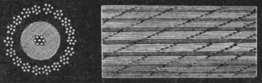
Fig. 1 |
The cable of 1858 (fig. 1) had for a conductor a copper strand of 7 wires, 6 laid around 1; weight 107 lb. per nautical mile. The insulator was of gutta-percha, laid on in three coverings; weight 261 lb. per nautical mile. The outer coat was composed of 18 strands of charcoal iron wire, each strand made of 7 wires, twisted 6 around 1, laid equally around the core, which had previously been padded with a serving of tarred hemp. Breaking strain, 3 tons 5 cwt. Capable of bearing its own weight in a trifle less than 5 miles’ depth of water. Length of cable, 2,174 nautical miles.
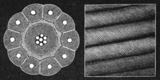
Fig. 2 |
In the cable of 1865 (fig. 2) the conductor was a copper strand of 7 wires, 6 laid around 1; weight 300 lb. per nautical mile. Embedded in Chatterton’s compound. Insulation was effected with gutta-percha and Chatterton’s compound. Weight, 400 lb. per nautical mile. The outer coat was 10 solid wires, drawn from Webster and Horsfall’s homogeneous iron, each wire surrounded with tarred Manilla rope, and the whole laid spirally around the core, which had previously been padded with a serving of tarred jute yarn. Breaking strain, 7 tons 15 cwt. Capable of bearing its own weight in 11 miles’ depth of water. Length of cable, 2,300 nautical miles.
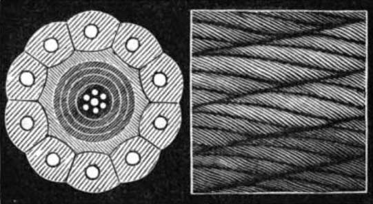
Fig. 3 |
The present cable (1866, fig. 3) has for a conductor a copper strand of 7 wires, 6 laid around 1; weight, 300 lb. per nautical mile. Embedded for solidity in Chatterton’s compound. The insulator is 4 layers of gutta-percha laid on alternately with thinner layers of Chatterton’s compound; weight, 400 lb. per nautical mile. The outer coat is 10 solid wires drawn from Webster and Horsfall’s homogeneous iron, and galvanized, each wire surrounded separately with 5 strands of white Manilla yarn, and the whole laid spirally around the core, which had previously been padded with a serving of tarred hemp. The breaking strain is 8 tons 2 cwt., and it is capable of bearing its own weight in 12 miles’ depth of water. This length of cable is 2,730 nautical miles, part of which is to be used for completing the cable that parted last year.
On the Two Atlantic Telegraph Cables.
By Fleeming Jenkin, Esq., C.E., F.E.S., in the Scientific Review.
Last year, in the October and November numbers of the Scientific Review, I had the honour to write two articles about the “Times’ Letters on the Atlantic Telegraph Expedition.” This year we have two cables, but no letters to write about; and it is satisfactory, on looking over my old articles, to find that I may refer the reader to them without having any corrections to make. The following is a description of the 1865 cable:—The conductor is a seven-wire strand of copper, weighing 300 lbs. per knot. The diameter of each wire is 0.048 inch; the diameter of the strand 0.144. This strand is insulated by four layers of gutta-percha and Chatterton’s compound, weighing 400 lbs. per knot, and measuring 0.464 inch in diameter. This core is served with, or wrapped in, tarred hemp, weighing about 2.2 cwt. per knot; and round this serving lie ten iron or steel wires, each of them separately covered with five strands of tarred Manilla hemp. The wires were made of Webster and Horsfall’s homogeneous iron, sometimes called iron, sometimes steel, and were ‘bright,’ not galvanized; the diameter of each is 0.095 inch, and the weight of all the wires is about 13.75 cwt. per knot. The weight of the hempen strands round all the iron wires was about 12.8 cwt., their lay about 3 inches. The diameter of the completed cable is 1.125 inch; its weight in air about 35¾ cwt., and in water 14 cwt.; its breaking strain 154 cwt., equal to 11,000 fathoms, or 11 knots of itself, hanging vertically in water. With this breaking weight, it stretched from 2½ to 4½ per cent. The mean resistance of the copper conductor per knot, at 24° centigrade, was 4.272, Ohm’s or B.A. units; the mean resistance of the insulator per knot, at the same temperature, was 349 millions of those units. The 1866 cable differs very little in construction from that of the previous year. No change was made in the copper or gutta-percha; the wires were made of a somewhat different quality of iron or steel, and were in part, I believe, supplied from France. They were galvanized instead of being bright, and were wrapped in white hemp instead of tarred yarns; the tar being no longer needed as a protection against rust. The cable was, I believe, a little lighter and a little stronger than that of 1866. But I have not at present such minute information concerning it as I have already given of its elder (or younger?) brother. The most important change consisted in galvanizing the wires, to prevent the rust which had actually been observed in some places on the 1865 cable under the tarred yarn. For all purposes of laying, speaking or testing, the two cables are practically identical. For repairs, the wires of the 1866 and the hemp of the 1865 cable will probably last longest. We have had convincing proof that the wires, even of the 1865 cable, do not seriously alter in strength during one year. The cables this year were paid out with similar machinery to that employed in 1865. The cable was held by a drum, round which it passed several times, just as, on a smaller scale, a rope is held by being passed round a bollard or the simplest form of capstan. The drum is prevented from turning too fast by a friction strap; this strap is weighted so as to produce exactly the retarding force required, and is, moreover, arranged, as in the annexed diagram, so that no change in the rubbing surfaces will affect the retarding strain. The retarding force, exerted by the breaks-trap, is obviously equal to the difference of tension on the ends a and b of the break-strap (fig. 4).
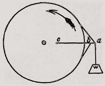
Fig. 4 |
There is a comparatively great strain on the end a, and a much smaller strain at b. The difference is the pull of the drum on the strap, or vice versa, of the strap on the drum. Let these ends, a and b, be attached to a lever, c a, working on a centre at c, and the weight, W, be hung at a; call the strain on the end a of the break-strap P, and that on the other end p; suppose, moreover, the two points a and b very near the circumference of the drum, so that their pull is sensibly at right-angles to the lever c a, instead of being at a sensible angle, as in the diagram. Then we have, taking moments round c—
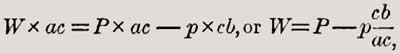 |
and when c b is nearly equal to a c, as in the case in practice, the weight,W, is sensibly equal to P—p, or to the friction caused by the break-strap. This, it will be seen, is true, whatever be the co-efficient of friction between the rubbing surfaces, or however much this may alter. If the friction increases a little, the weight, W, rises a little, and this loosens the break-strap by placing the lever, c a, at a slight angle upwards, from c to a. If the co-efficient of friction diminishes, the weight, W, falls a little, tightening the break-strap.
This arrangement, invented by the late Mr. Appold, may be used as an accurate dynamometer, to measure power transmitted by a shaft, and effectually prevents a greater strain than is desired coming on the cable through the agency of the break-drum, which does not, therefore, require any extraordinary attention. Certain jockey pulleys, each with its little break-strap, are placed between the ship’s hold and the break, and also retard the cable a little; their chief use is to hold the slack end of the cable taut on the drum, just as a man or two may be required to hold the slack end of a rope passed round a capstan. The rope, on leaving the break-drum, passes under a pulley on a weighted lever and up again to the large stern sheave from which it shoots out, forming a very small angle with the horizon, and just touches the water about 200 feet astern. The weighted pulley riding on the flat bend of the cable is commonly called the dynamometer, because it weighs or measures the strain on the cable: as the strain increases the weight rises, and the bend in the cable becomes flatter and flatter. This dynamometer is therefore an extra safeguard, showing that the break and other retarding machinery are working properly. Inventors should turn their attention to other matters than to devising fresh modes of paying out cables. The arrangement just described works admirably, and has paid out the 4000 miles of Atlantic cable without a hitch.
One dangerous incident certainly did occur. Several turns of the cable came up entangled one with another out of the hold in such condition that they could not be passed over the drum. The paying out had to be stopped instantly, and a very considerable time had to be spent in disentangling the rope, while great and dangerous strains could only be kept from arising by a skilful management of the ship.
The retarding strain on the cable was about 12 cwt. The cable would bear nearly 8 tons; and these figures show the merit of the form adopted. The 2400 fathoms of the cable, if hanging vertically from the ship in water, would have weighed 35 cwt. The weight of the cable, as it actually stretched from the ship to the bottom in almost a straight line, upwards of 16 miles long, was upwards of 11 tons. The strain on the cable, if it had been hanging in a catenary curve, emerging from the water at the angle observed (about 9° 30'), would have been upwards of 100 tons; but the actual strain was only 12 cwt. And this observed strain entirely agrees with that to be deduced from the mathematical theory which was first published by Prof. W. Thomson in the Engineer (October 1857), and is fully treated of by Messrs. Brook and Longridge in a paper read before the Institution of Civil Engineers in 1858. The chief conclusions of this theory may be stated as follows:—To lay any cable, however light, quite taut we require nearly the tension due to a weight of the cable hanging plumb from the surface to the bottom: but, by increasing the bulk of any cable, if we do not at the same time increase its weight in water, we may, by laying a little slack or waste cable, diminish the tension very greatly. The explanation of this is that the increased bulk increases the resistance which the water offers to being displaced by the cable as it falls, and also increases the friction by which the water tends to prevent the cable from slipping through it end-ways. By this frictional resistance and resistance to displacement, the water itself bears up a great part of the weight of the cable, and it bears up more the faster the ship goes and the faster the cable is paid out.
The testing arrangements this year were, in every respect, different from those of 1866. To describe them in any detail would require a separate article, but the result of the system may be given in a few words. A constant insulation test was maintained on board ship. A second insulation test was maintained on shore. The ship could signal to the shore, or the shore to the ship, without destroying or altering the insulation test on ship-board . And, finally, if a fault did occur, its position could be almost instantly ascertained by the double ship and shore-readings; unless, indeed, the fault were so bad that all communication with shore was broken, in which case no difficulty would be experienced in fixing the position of the fault by the single ship’s test. By this system a fault could not possibly occur without being instantly observed, for at no time was the insulation test abandoned; and yet the frequency of telegraphic communication with the shore, by which ship’s news could be sent and shore news received, instead of being diminished, was increased to the utmost. It would be difficult to praise too highly this novel and beautiful system carried out by Mr. Willoughby Smith, under Prof. Thomson and Mr. Varley, and arranged by him conjointly with them.
Whether the injuries caused last year were accidental or the result of malice will now probably never be known. No similar injuries occurred this year, and the fault which led to the loss of the cable in 1865 has not been recovered, so that we remain ignorant of its nature.
The total length of the 1866 cable is about 1858 nautical miles, and the distance run was 1669 miles; that of the 1865 cable, 1896 nautical miles, and the distance run about 1670 miles. The insulation resistance per knot of the 1866 cable, when laid, was, by Mr. Latimer Clark’s tests, 2,200 millions of B.A units. That of the 1866 cable has not been published, but is still higher. The great increase in this resistance over the figures given above is partly due to the low temperature of the bottom of the ocean, and partly to the great pressure which is invariably found to improve the insulation.
The recovery of the 1865 cable in good condition is obviously much more important as an engineering achievement than the submersion of many new cables. It is also more important to the shareholders, for it removes from their property the imputation of being liable to any excessive risk of total loss or rapid depreciation. The public has never distinguished between shallow and deep-sea cables as an investment: the former have long been a safe property, but the many deep-sea failures threw discredit on all submarine cables. Now this discredit is, or should be, wholly removed, for cables are actually safer in deep seas than in shallow ones; and it was only because of the belief that one fault or flaw in a deep-sea cable must be fatal to it that engineers on all occasions chose a shallow rather than a deep-sea route. Even now I should personally prefer shallow water, because, even if the outer covering decays, the valuable core of the cable can be recovered from small depths; but in the Atlantic, if the steel or iron rusts, and any accident occurs, the cable can no longer be repaired . It may be urged, with much show of reason, that no accident can occur in great depths after the cable has been down long enough to lose its outer sheath; but I am not bold enough myself to set bounds to possibilities. Meanwhile it is very encouraging to hear that the 1865 cable, when recovered, showed both hemp and iron to be apparently as strong and sound as ever; while the electrical tests proved that the core had in no way deteriorated. It is one of the great advantages of the present accurate system of testing that enables the electrician to pronounce with certainty upon a point of this kind.
The process by which the cable was recovered was of the simplest kind. The grapnel, a sort of four-pronged small anchor, was simply dragged along the bottom of the sea by a very strong steel rope. The strain on the steel rope was watched by aid of a dynamometer, similar to that already described, and when any considerable increase of strain was observed, the cable was supposed to be caught: the picking-up gear was started, and slowly hauled up the steel rope by the aid of a drum, exactly like that used for picking up, but placed near the bows of the ship. If the strain continued to increase steadily, even after the grapnel was known to be off the ground, then the cable was certainly hanging to it. The strain caused by the weight of the steel rope, by its resistance to the water, and by the flukes of the grapnel as they dragged along the sand, ranged from 6½ to 9 tons; when more than this strain was observed, the cable was always hooked. It was just possible to haul the cable by main force to the surface without breaking it. To explain this, I cannot do better than quote a short extract from a lecture which I gave at the Society of Arts, and published in their Number for the 16th Feb., 1866:
If a cable were laid absolutely taut along the bottom of the sea, when hooked by the grapnel it would rise a little way in virtue of its elasticity; if it stretched one per cent., by the time ten miles of it were off the ground the apex would be half a mile from the ground—a result few are prepared to expect; but the strain on the cable where caught would be very great, being equal to the weight of about twenty-four miles of the cable, though the weight on the grapnel rope would be only that of ten miles of cable. The result, therefore, of trying to raise a cable such as the Atlantic, laid taut, would certainly be to break it; but cables are not laid taut in deep water, and the Atlantic is laid with a mean slack of about twelve per cent., and in the last days we may even count on fourteen or fifteen per cent, slack; that is to say, for every 100 miles passed over, 114 or 115 miles of cable were laid. Lay on the floor 114 inches of chain, between two points 100 inches apart; lift it in the middle on a hook: the two ends will hang down in catenary curves, and when the cable at the extremities is just off the floor, the hook will be 23.3 inches from the floor. Quite similarly a cable laid with fourteen per cent, slack will, when caught by the grapnel, hang in two half catenary curves; and by the time 11.4 miles of the cable are off the ground, the grapnel will be 2,330 fathoms from the bottom—i.e., at the surface of the Atlantic.
The strain on the grapnel rope will be the weight of the cable lifted, or about 11.4 miles; the strain on the cable itself at the point of suspension will be much less, being only about 3½ times the weight of the cable hanging vertically, or say eight miles of cable. Observe that the strain on the cable and the weight of the cable are not synonymous.
When the two ends hang plumb, the strain on the cable at the top is half the weight of the cable carried.
When there is little slack, the strain is much greater than the weight carried.
If the depth were only 2,000 fathoms, the strain on the cable when brought to the surface would only be equal to the weight of about seven miles of cable. Moreover, the actual cable is not held at any point, except by its own weight, and there will be a pull at the bottom tending to haul in slack towards the grapnel amounting to several tons: but, even without counting upon slack obtained in this way, it is clear that if the cable will bear eleven miles of its own weight, it could, under favourable circumstances, be hauled to the surface by a single grapnel.
On one occasion the cable actually was thus lifted by sheer pulling; but at the very moment of apparent success it parted, showing that, as I anticipated, the practical chances of success by sheer pulling in the deepest water would not be very great. The engineers in charge of the expedition were perfectly well aware of this, and their object was first to try to hook the cable so near the end that it would draw along the bottom, and, hanging down nearly vertically on either side of the grapnel, come up with comparatively little strain.
This they did not accomplish; and, after breaking the cable several times, and actually getting one of the short pieces broken off on board, they shifted their grappling ground to a point nearly 100 miles from the end, in rather shallower water—viz., 1,900 fathoms. Here the engineers practised the simple and safe plan of hooking the cable with two ships—the Great Eastern to the west, next Ireland, the Medway to the east, with orders when she hooked the cable to heave up as rapidly as possible, and to break the cable, so as to take off the strain from the Great Eastern’s grapnel . It does not appear, from the only narrative yet published, whether the Medway actually did break the cable, or whether her pulling had only the effect of dragging sufficient slack from the eastward to allow the Great Eastern to get up the cable without too great a strain. Either result was possible; but, at any rate, the cable this time was safely made fast to the Great Eastern, and the 100 miles lying towards America were cut away, and so, as I understand, were lost for ever: so that the nature of the last 1865 injury will probably now never be known. The incidents described in the long diary of the dredging are wonderfully like those met with in shallow water; and the time occupied was no greater than is frequently required to repair cable in thirty fathoms. The completion of the 1865 cable was looked upon by every one as a matter of course as soon as the old end was on board; although, six weeks previously, laying 600 or 700 miles of cable in the greatest depth of the Atlantic would have been watched by all with anxiety, if not fear.
Some uses of the double cable will be peculiarly interesting to science. The laws of transmission of electricity can by their aid be studied as can be done by no other means. So long as one remains good, the position of any fault can be determined with extraordinary precision. By using one as a return wire, probably messages may be transmitted even during violent magnetic storms, which would stop work with one wire only. If this result does not follow, we shall at any rate obtain new and valuable information as to the probable course of earth currents and magnetic storms. When the law of transmission has been verified, the cable may be used for astronomical observations of great importance. The resistance both of copper and gutta-percha ought to tell us whether any variation occurs in the temperature of the bottom of the sea, and even whereabouts any such alteration occurs. I hope the Directors will show a liberal spirit, and allow such experiments as these to be made by competent men, and so, to put the matter fancifully, show their gratitude to science. I have not ventured to praise the men in charge of the expedition. They require no acknowledgment from any one: their work stands patent to all. But I should be glad sometimes, in connexion with Atlantic cables, to see some mention of Sir Charles Bright, Mr. Whitehouse, and others, who acted as pioneers, and at least cleared the way for the final and successful attack.
Reference to other papers and articles for which there is not space in present volume.
(All the dates refer to the year 1866.)
Electro-Telegraphy and Electrical Science,—Engineer, Jan. 12th.
Transmitting Apparatus of the Atlantic Cable,—Engineer, June 13th, Illus.
Laying Telegraph Cables,—Engineering, Feb. 23d, p. 118.
Recovering Apparatus for the Atlantic Telegraph,—Engineer, June 22d, p.
447, Illus. Jones’ Tablet Telegraph,—Scientific Review, Oct., p. 115, Illus.
Atlantic Telegraph,—Engineer, July 27th, p. 61, Illus.
Repairing Submarine Cables,—Engineering, May 11th, Illus.
Atlantic Telegraph,—Engineering, Nov. 2d, Illus.
Submarine Telegraphy,—Scientific Review, March 1st.
The Rise and Progress of Telegraphy,—Engineer, Feb. 16th.
The Picking up of the Atlantic Telegraph,—Mech. Mag., Sep. 7th, p. 141.
Simpson’s Typo-Telegraph,—Engineering, July 20th.
Automatic Telegraphy by A. Bain,—Journal of Society of Arts, Jan. 19th,
Illus.
Deep Sea Telegraphy,—Scientific Review, Aug. 1st.
Signalling Speed of the Atlantic Cable.—Engineer, Aug. 3d.
Testing Submarine Cables,—Mech. Mag., April 6th.
Return to the Atlantic Cables index page
|
