WEEKLY EVENING MEETING,
Friday, February 15, 1867.
Sir Henry Holland, Bart. M.D. D.C.L. F.R.S. President, in the Chair.
Cromwell F. Varley, Esq. M.I.C.E. M.E.I.
On the Atlantic Telegraph.
The object the speaker had in view was to demonstrate (for the first time in public) a few of the more subtle phenomena, which present themselves when attempting to work long submarine cables, and to show how the disturbances arising from earth currents are sufficiently neutralized to prevent them from interfering with the telegraphic signals.
For this purpose he had two artificial telegraph cables, the one representing the Atlantic Telegraph cable, the second one being made 40 times slower, so as to represent the phenomena which would present themselves on a cable of the same dimensions per nautical mile as the Atlantic Telegraph, but 13,000 miles in length, long enough to reach from England to Australia.
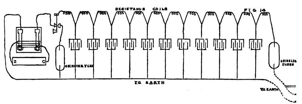
The former artificial cable consisted of 11 coils of fine German silver wire, having together the same resistance as the actual Atlantic cable. The phenomena of electro-static induction were given to this conductor, by attaching at each of the junctions between the coils a large condenser. (Vide Fig. 14.)
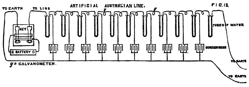
The second or slow artificial line consisted of 11 glass tubes; and the apparatus was so constructed that by turning a handle the condensers could be removed simultaneously from the resistance coils, and reapplied as often as necessary. A galvanometer was inserted between each of the tubes in the latter circuit.
The glass tubes were filled with a solution consisting of 08 parts pure water and 2 parts sulphate of zinc.
The metal poles dipping into the solution were composed of zinc amalgamated; amalgamated zinc electrodes in a solution of sulphate zinc being almost entirely free from polarization.
The reflecting galvanometers differed from those hitherto used in the following respects:—the mirrors consisted of lenses ground and polished, instead of flat microscope glass, the tubes containing the mirrors had glass ends and were filled with pure water, which cut off the tremors of the room, and brought the instruments to rest in the fraction of a second.
Each mirror was half-an-inch in diameter, and with its magnet weighed 2 grains, and was suspended by 3 cocoons of silk 1/16th of an inch in length.
The time allowed for this discourse only permitted of a cursory examination into two of the many interesting inquiries connected with the Atlantic Telegraph.
The speaker observed:—“The press had (imperfectly) familiarized the public with the mechanical operations of manufacturing and laying the cables, as well as with the means adopted for navigating the ship across the ocean.
“The method adopted for testing the integrity of the insulation of the cable as well as of its conducting power were partly brought under the notice of this Institution by Sir William Thomson not long since.”
Light and radiant heat travel through space with a definite velocity; electricity does not. The waves of light do not flatten out or elongate during their flight over millions and millions of miles. For example, suppose the star Sinus were suddenly covered by a screen for ten minutes and then uncovered again, the star would still appear on this earth to shine continuously for about twenty years after the screen was applied, when it would be suddenly extinguished for just ten minutes, and then re-appear.
Electricity in passing through a cable begins instantly to appear at the distant end, but in strength far too weak to be measured; after the lapse of a certain time definite for each particular cable, it begins rapidly to augment in power and continues to approach to a definite limit of strength.
The reason for this will appear when the construction of the artificial Atlantic cable is considered.
Electricity is popularly supposed to have a definite velocity, like light; this is not so. The question—what is the velocity of electricity? cannot be answered unless other conditions are given; for instance, it begins to arrive at the distant end instantaneously, but to reach its maximum strength would, strictly speaking, require eternity and a day; while to reach half its maximum strength would have occupied a time of 6 a, this quantity a being a definite time dependent upon the dimensions of the cable.
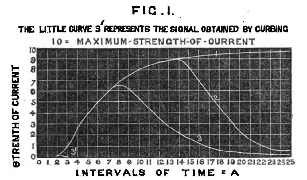
Fig. 1, curve No. 1, represents the strength of the current at the distant end of the cable, after the lapse of periods of time represented by the figures under the diagram," the maximum strength which the battery can produce through the cable being represented by 10.

Fig. 1 |
The figures on the horizontal line represent equal periods of time: a.
The figures on the vertical line represent the strength of the current. On connecting one end of the cable to a battery whose other pole is to earth, no sensible current is visible until after the lapse of the period a, when the current has a strength of a little more than a thousandth part of that which the battery is capable of producing.
When the cable is fully charged, the current attains its maximum strength, which is represented in the diagram by the line opposite the vertical figure 10. After the lapse of 4 a, the strength of the current is about one-fourth of this maximum power. After the lapse of 6 a it has a strength equal to half the maximum, and for greater periods of time the strength of the current goes on augmenting if the battery be continually applied, as shown by curve No. 1. But although it approaches to, it never, in strict language, actually attains the absolute maximum strength 10. For instance, after 20 a, the strength of the current is about 98 per cent. of the maximum.
The curves 2 and 3 show the rise and fall of electric currents at the distant end after the cable has been connected to the battery for intervals of time corresponding to 12 a and 6 a; and after such contact with the battery, the cable has been connected to the earth again. This is about as quick as it is possible to signal through a submarine cable with the ordinary Morse instrument. No. 2 represents a “dash;” No. 3, a dot.
The little curve 3' represents a signal whose strength is only 1 per cent. of the maximum strength. Such signals are only to be obtained either by the curb-key or the use of condensers at the end of the cable, as explained further on.
It will be seen that considerable time must be allowed to elapse after the impulse has been given for a dot or dash before the cable has sufficiently discharged itself to permit of a second intelligible signal. It is evident from the above diagram that in order to get rapid signalling through an Atlantic or other long cable the apparatus must first of all be very sensitive, so as to give as early indication as possible of the arrival of the electric current, and the moment such indication begins to be produced the line must be discharged as quickly as possible, in order that a second signal may be made to follow quickly afterwards.
On January 20,1854, Dr. Faraday, in a discourse at the Royal Institution, [Proceedings of the Royal Institution, Vol. I., p. 345] described a number of experiments which he had made with a hundred miles of gutta percha-covered wire, and also some experiments upon 1500 miles of line between London and Manchester. But on the table before the speaker was an artificial representation of a cable 13,000 miles in length, by the aid of which the same phenomena amplified and many others were exhibited.
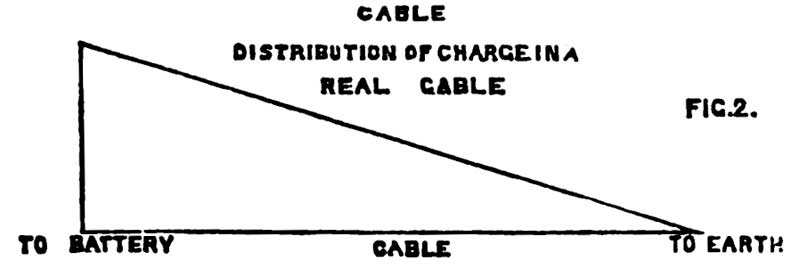
A telegraph cable is a long Leyden jar, one end of which is attached to the earth, whilst the other is attached to a source of electricity each time a signal is to be produced. If the cable be connected to a battery for a long time, the strength of the charge in the different parts of the cable will be shown by the diagonal line, Fig. 2, being nothing at the end connected to the earth, and equal to the full power of the battery at the other.
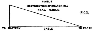
Fig. 2 |
Fig. 3 shows the distribution of the charge in the artificial line.
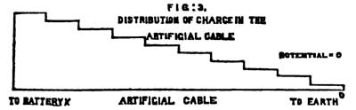
Fig. 3 |
Fig. 6 represents a section of the core of the Atlantic Telegraph cable. The seven small circles are sections of the seven copper wires constituting the conductor—the interstices between the wires are filled with a mixture of gutta percha and wood pitch. Four coatings (or tubes) of gutta percha united together by pitch and gutta percha form the insulating medium. The reasons for using seven wires instead of one solid conductor, are first, to avoid the risk of a flaw or break in the conductor, which would be fatal to the line; secondly, to reduce the rigidity of the copper.
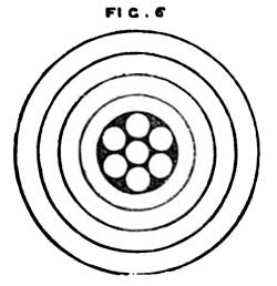
Fig. 6 |
The weights per nautical mile (2029 yards) are—copper, 300 lbs. avoirdupois; gutta percha, 400 lbs.
When such a core is submerged the copper conductor forms the interior coating; the gutta percha, the insulating medium; the water, the exterior coating of a Leyden jar.
Figs. 13 and 14 represent the artificial cables.

Fig. 13 |
When the cable is at rest, the two ends are connected to the earth; on depressing the telegraphic key, a battery is inserted between the earth and the cable, and a current immediately flows in at the sending end; the keys in the diagram are double ones; on depressing the right-hand key, the positive or copper pole of the battery is connected with the cable, while the negative or zinc pole is left in connection with the earth; if the left-hand key be depressed, the right-hand key being up, the negative or zinc pole of the battery is connected with the cable, while the positive or copper pole remains connected to the earth. The second key shown in Pig. 14 was used as a switch to connect the cable at pleasure either to the battery key or to the Geissler's tube, to show the escape of the charge in the cable from both ends of the circuit.
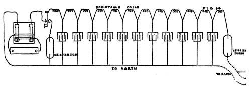
Fig. 14 |
On depressing one of the keys, the battery is inserted between the earth and the cable; a current immediately flows; after passing through the first resistance it meets with the first condenser; here it finds two channels, namely, the condenser and the other resistance coils, forming the remainder of the circuit.
At the first moment of time the condenser being empty, it offers no appreciable opposition to the electric current which commences charging it, and therefore at the first instant of time nearly the whole of the current is spent in charging the condenser. No sooner, however, has the charging commenced than this charge begins to oppose the further flow of electricity into it; a current then flows through the second coil; its strength is dependent upon the potential for the time being of the charge in the first condenser. Example: suppose the potential of the battery to be 100 (and its resistance practically nil), let the resistance of each coil be 1 at the first moment of time; as the first condenser offers no sensible resistance, there will be a resistance of 1 only in circuit. By Ohm's law the strength or volume of the current is—
Where I equals the volume of the current, E the potential of the battery, E the resistance in circuit.
After the lapse of a very short interval of time, the first condenser will have become charged to a potential of 1/100th part that of the battery, viz. 1, at that moment of time, as there will be no sensible charge in the second condenser; the strength of the current in the second resistance coil will be 1/100th part the strength of the current that flowed through the first coil at the first moment of contact with the battery.
Thus it will be seen that no appreciable current will be found in any of the other resistance coils until an appreciable charge has reached the condenser immediately preceding it.
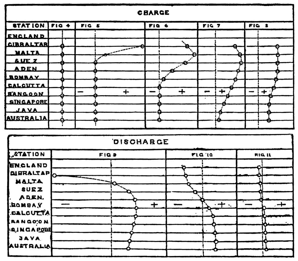
If ten galvanometers were inserted in a long cable at equal distances, it would be seen that at the first moment of contact with the battery, the current rushing into the cable is vastly greater than it is a few moments afterwards; this was illustrated by the speaker on the large artificial cable represented in Fig. 13. The ten galvanometers were placed one above the other; they were carefully adjusted so that the ten images which they reflected from the electric lamp upon a large white screen formed a vertical line when no current was passing (vide Fig. 4 above). The galvanometers were all of equal sensibility.
To familiarize the audience with the relative positions of the different galvanometers, the speaker considered the upper part of the screen to be England, the lower part the Antipodes.
The 1st station was named Gibraltar, the 2nd Malta, the 3rd Suez, the 4th Aden, the 5th Bombay, the 6th Calcutta, the 7th Rangoon, the 8th Singapore, the 9th Java, the 10th Australia.
No galvanometer was inserted at England, because the discharge from the cable through it to the earth was so powerful that the magnetism of the needle was reversed by it, and the indications rendered alternately the opposite of the truth.
The speaker first of all connected the condensers of the artificial line all together, and charged them with a battery of 800 cells, Daniel's battery. On discharging them by means of a sheet of tinfoil, a loud report, a brilliant flash, and an irregular hole five-eighths of an inch in diameter were the result.
The second experiment consisted of connecting the 800 cells with the artificial Atlantic cable (Fig. 14), the condensers being removed from the resistance coils. The instrument used to show the passage of the electric current was an exhausted glass tube (a Geissler's tube), whose resistance was such that it would just allow a current of 400 cells, Daniel's battery, to pass from wire to wire. This tube formed a ready method of showing when the charge at the Newfoundland end reached half the potential of the battery. The condensers being removed from the artificial line, the current appeared instantly at the Newfoundland end, and disappeared instantly upon the connection between the battery and the cable being broken at the English end. When the condensers were applied, an interval of 3 or 4 seconds elapsed before the current appeared; and on breaking the connection between the battery and the cable at the English end, the current still continued to flow out of the Newfoundland end for many seconds afterwards.
The experiment was varied by connecting the cable to the 800 cells, until, by the brilliancy of the Geissler's tube at Newfoundland, the cable was seen to be nearly fully charged; the battery connection was then broken at the English end, and the cable connected to the earth by a second Geissler's tube, the latter shone with a more brilliant light than that at Newfoundland, because the charge in the cable near the battery was greater than at the distant end, thus forming a rough but very pretty illustration of Figs. 1 and 2. The tube at the English end continued to shine for several seconds after the Newfoundland end had gone out, because the charge at the end of the cable near the battery was greater than at the other end.
A smaller battery was then connected with the long, or Australian, artificial line. A bundle of rays from the electric lamp was thrown upon the 10 galvanometers, each of which reflected a little sun-like spot upon a large white screen, forming, when no current was passing through the cable, a straight vertical line of luminous points (vide Fig. 4). On depressing the right-hand key, Gibraltar almost immediately responded, and when it had travelled about 6 feet over the screen (vide Fig. 5), Malta began visibly to move.

Figs. 4-11
(In Figs. 10 and 11 the engraver has made a mistake,
and inserted one galvanometer too many.} |
Later still the current at Gibraltar decreased considerably in strength (Figs. 6, 7, and 8), owing to that end of the line becoming charged. Fig. 7 shows approximately the appearance presented after the cable had been connected to the battery 14 seconds; and Fig. 8 shows the appearance after the lapse of nearly a minute, when a powerful current was rushing out at the Australian end. The English end was then removed from the battery and connected with the earth; and quickly after the Gibraltar spot rushed across to the other side of the screen, indicating the rolling back of a powerful current to the earth. This was followed shortly afterwards by Malta, Suez, and Aden. Bombay came only as far as the zero line, at which time the currents in the different parts of the cable were flowing out at each end, leaving Bombay neutral. It was some minutes before the cable was sufficiently discharged to allow the ten spots to come near enough to the zero line to admit of a second experiment.
The curves produced at successive intervals of time while the cable was discharging are shown by Figs. 9, 10, and 11. Fig. 9 giving the position of the spots a second after the English end was connected to earth; Fig. 10, the appearance shown at a still later period; Fig. 11, after the lapse of about a minute. Here it will be seen the cable having become charged had to discharge itself by pouring its electric charge out at each end.
When a succession of signals was sent into the cable by alternately depressing and elevating the key, for periods of five seconds each, these impulses produced waves which could be distinctly traced as far as Aden, where their individuality became lost. The little spots beyond this station showed the presence of a current resulting from the combination of these successive waves.
The speaker then pointed out his methods of clearing the line after each impulse. In 1853-54 he invented a plan which consisted of sending after each positive current, a negative current—a plan which is now generally used in working submarine lines.
In 1856 he invented a plan which consisted of sending a strong positive current of definite strength and duration into the line, followed by a weak positive current to produce a signal; this being followed by a strong negative retreat, succeeded by a weak negative current to clear the line. This system was a great improvement upon the former.
In 1858 Professor Sir William Thomson proposed the use of three currents of equal duration but irregular strength and alternate signs, which produced a still more rapid result.
In 1863 the speaker found, by experiments on his artificial line, that by using a succession of four or five currents, all of the same strength but varying in duration, greater rapidity could be secured.
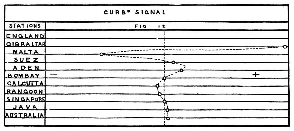
For example, first a positive current, followed by a negative of longer duration, followed again by a positive current of much less duration; then a shorter negative current, and that again by a very short positive current, produced a succession of positive and negative waves throughout the line: the result of all of which was at the Australian end one very small positive wave, perfectly distinct, the rest of the line being left almost immediately entirely free from all traces of electricity, ready for the production of a second signal. This is shown by Fig. 12.
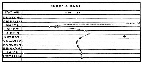
Fig. 12 |
In the previous experiments, when an impulse had been given the charge had to find its way to the earth through the two ends of the cable.
By experiments on actual cables the speaker had at an early date ascertained that the rate of transmission through a cable is independent of the potential or intensity of the battery, and that it varies inversely as the square of the length of the cable, excepting in the case of very short cables thickly covered with iron, where the retardation caused by the magnetic inertia of the iron forms an item of some importance; and in the foregoing experiments it has been assumed, which is really the case with such a cable as the Atlantic, that this retardation is too small to be worthy of consideration.
Professor Thomson, by mathematical reasoning, has calculated, and the artificial cable has demonstrated, that the strength of the current at the distant end varies, as shown in Fig. 1; and that with a given potential or intensity there is no possible means of expediting this rate of arrival: and therefore, in order to get high speed, highly sensitive instruments must be used, and so soon as a visible indication has been produced at the distant end, the cable must be cleared of its charge, so as to admit of a second impulse or signal being given.
The instrument known as the curb key seems to carry this to the utmost limit, and its success depends upon the following consideration:—If the line be cut in half, the speed of transmission^ increased four times. If now one-half the cable were made positive while the other half was made negative, it is clear that while the first quarter of the cable which was negative is discharging to earth, and whilom the last quarter of the cable which was positive is discharging to earth, the two intermediate quarters would discharge by rushing into each other: consequently the electricity having a shorter distance to travel, the discharge is effected much more quickly.
Fig. 12 represents the currents in the cable, after a curbed signal of five currents producing three positive and two negative waves in the cable, the first positive current to produce the signal was followed by a longer negative current to cut off the upper portion of the curve No. 1, Fig. 1. This would have produced a powerful negative signal, therefore a shorter positive current was sent into the line to curb it, and that followed by a still shorter negative, followed by a very short positive.
These five alternate currents were all sent into the line before any signal was visible at Australia.
Almost immediately after the appearance of the current at the Australian end the alternate waves neutralized each other, and the ton spots fell rapidly upon the zero line, showing that the cable was discharged throughout.
The little curve 3' Fig. 1, represents a signal curbed down to nearly 1 per cent. of the original wave, while the big curve 3 represents the short signal of the ordinary Morse key, the latter requires at least 18 a for its formation, while the former can be made in from 2½ to 3 a.
There seems a definite limit beyond which the curbing cannot be carried with advantage. The eye of the operator can read the signals even when considerably distorted; and when the curbing is carried below the 1/100th part of the original wave, which the speaker has done upon the Atlantic cable itself, an interval of time has to be left between each signal to admit of their being individualized; i.e. the signals will not bear distortion, and the line must be more thoroughly cleared before a second signal which shall be distinct can be made to follow.
The speaker explained the plan he had invented in 1862 for expediting the signals through the cable, and for cutting off the disturbances arising from the Aurora Borealis, and which were generally designated “magnetic storms.”
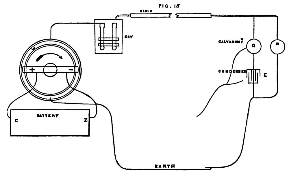
These phenomena are not unfrequently experienced simultaneously over the greater part of the earth, and are sometimes so powerful that the earth at Ipswich has been found to be + or – to the earth in London to the extent of 140 cells Daniel's battery. These currents do not change suddenly like electric signals, but go gradually over from positive to negative. The speaker had constructed an apparatus (vide Fig. 15) for imitating these currents. An annular trough containing sulphate of zinc solution was connected at opposite points to the earth and to the cable (through the telegraph key). A fly-clock rotated the crossbar as shown by the arrow in the diagram. From this crossbar depended two pieces of amalgamated zinc connected with the two poles of the battery, when the latter were at right angles to the line connecting the cable with the earth, viz. as in the figure, no current flowed into the cable. When this crossbar had moved 90° from the position shown in the diagram, a positive current was flowing into the cable; on its moving 180° more the current had changed sign and reached its maximum negative. This apparatus performed the half revolution in 40 seconds. The speaker stated that he had never seen, in all his experience, an earth current change from maximum positive to maximum negative in a shorter period than 60 seconds, and that only once; the change was often spread over an interval varying from five to ten or more minutes.

Fig. 15 |
At the Newfoundland end of the cable, a reflecting galvanometer was placed between the earth and the cable, whilst a second galvanometer was placed, on Mr. Varley's plan, between a condenser and the cable, the other polo of the condenser being connected with the earth. The moment a current began to arrive at the distant end, it was shown upon both galvanometers; but as soon as it had acquired a uniform strength, the condenser, being charged to that strength, cut off all further electricity, and the second galvanometer returned to zero, while the first one remained deflected. The amount that the second galvanometer was deflected did not depend at all upon the amount of current passing through the cable, but simply upon the rate at which its potential varied, and according to which the condenser charged or discharged itself. The earth currents sent the ordinary galvanometer image running from right to left twenty or thirty feet, right off the screen in fact, but the other one simply moved three inches, because the rate of variation of potential being slow the condenser charged slowly.
The effect of the condenser on the latter galvanometer is at the first moment to offer no resistance to the passage of the electric current. Suppose a current of a force 1 to arrive at the distant end, the current splits, part running through the galvanometer D to the condenser, the other through the galvanometer or resistance B to the earth.
As soon as the condenser becomes charged to the power 1 the current in D ceases, if now the current increase from 1 to 2 the condenser E will become charged to 2, and while charging the galvanometer D will indicate the presence of a current; but as soon as the condenser is charged with the same power as the cable, the current in D ceases. Thus then the galvanometer and condenser D, E do not measure the strength of the current flowing through the cable, but simply indicates alterations of the potential.
Suppose the cable and condenser charged to a potential of 100, D would show no current; if anything suddenly augmented this potential to 101 the condenser would be charged to 101, and the variation of potential would be indicated. Suppose now that the charge were decreased from 100 to 99 the potential of the condenser would be reduced to 99 by discharging itself into the cable, producing a current in the opposite direction of a power of 1.
Thus then the strength of the current in D is entirely dependent upon the increment or decrement of potential, and not upon the strength of the current flowing through the cable. Suppose now an earth current of a power of 100 to pass from + to – in 60 seconds. A signal through the Atlantic cable is produced in about a quarter of a second.
If the strength of the signal be but 1/10 of that of the earth current, yet as the rate of variation is 240 times greater, the signal while it lasts will be 24 times as strong as the earth current, and so the weak rapid current produces a signal, while the strong, by slowly changing earth currents, produces one too feeble to interfere.
The same disposition of apparatus greatly accelerates the speed of signalling, and affords a near approach to the rapidity attained by the curb key; this contrivance, however, can be used with advantage in conjunction with the curb key.
The speaker demonstrated this by sending signals through the artificial Atlantic cable, from a very much weaker battery than that used to produce the earth currents; however, the rate of augmentation of potential of these small signal waves being much greater than the rate of variation of potential of the great earth current wave, sharp clear signals were produced upon the second galvanometer. So by this extremely simple contrivance the small ripples upon the back of the big earth current wave were, practically speaking, entirely detached, and clear signals produced, which despised altogether the great swell which had rendered the first instrument altogether useless. A number of words were spelt through the cable to illustrate the fact.
In concluding, the speaker remarked that it was upon the data furnished by this artificial cable that he designed the present Atlantic cables, and that without it he could not then have guaranteed eight words per minute without a core whose conductor and insulator were each 60 per cent, greater than the present, which consisted of 300lb. of copper and 400lb. of gutta percha to the mile; and he added that it was at least some reward for the years of arduous labour he had had in connection with this great enterprise to find that everything he had predicted as to the capabilities of the cables had been entirely verified.
[Samples of the 1865 and 1866 cables were exhibited, also a piece of the cable which had been for more than a year two miles below the surface of the Atlantic Ocean.]
The speaker gratefully acknowledged the kindness of Dr. Tyndall, who had provided him with the electric light and his assistant to manage it.
[C.F.V.]