Introduction:
Allison Andrew Clokey (1892-1966) was an electrical engineer who specialized in telegraphy and submarine cables. He was awarded 38 US patents; the first in 1915 for a telegraph call box, and the last in 1940 for a constant temperature fluid mixing valve. His first three patents, issued in 1915, 1916, and 1917, were all assigned to Western Union Telegraph Company, probably his first employer after graduation. Clokey’s residence in those patents was given as Jersey City, New Jersey. He became a Member of the American Institute of Electrical Engineers in 1916 [1].
Some time after the USA entered the First World War in 1917, Clokey joined the Signal Corps. After the war, with the rank of Captain, he directed the Cable Engineering Section of the newly formed Engineering and Research Division of the Signal Corps [2]. This Division was created on July 6, 1918, and the Cable Engineering Section was discontinued on January 15, 1919. Clokey left active duty in 1919 on the disbandment of this section, and subsequently held the rank of Major in the Signal Corps Reserves, attached to the 303d Signal Battalion [3]. In 1920 the Western Electric employee magazine listed him in a section titled Employees Who Were Decorated or Cited: "A.A. Clokey, Captain, Signal Corps, Certificate from Commander-in-Chief for meritorious service" [4].
In 1919 Clokey was elected to Associate Membership of the American Association for the Advancement of Science, his profession at that time given as Research Engineer at the Western Electric Company of New York, the manufacturing arm of the Bell Telephone System [5]. His first post-war patent, filed in May 1920 (although it was not issued until 1926), was assigned to the Western Electric Company, and lists his residence as Rutherford, New Jersey, as did all his subsequent patents.
In 1923 School Executive magazine reported that: “Allison A. Clokey is the new president of the Bergen County (NJ) Federation of
Boards of Education, succeeding Thomas R. Cox.” He was also president of this board in 1941 [Bergen County Panorama].
The Bell Laboratories Record noted in 1924 that: “The trial equipment at Horta was installed during the latter part of 1924 under
the direction of Allison A. Clokey, with the assistance of Mr. Knoop,” and in 1926: “Allison A. Clokey has developed terminal apparatus for submarine cables; in his
group has been done all the engineering of the new multiplex system now being installed on the Azores cable.” This work would have been on the 1924 New York-Azores cable, the first commercially operated cable to use permalloy loading for improved speed, developed by the Western Electric Company.
A 1927 article by Clokey in the Bell System Technical Journal [6] shows him working for Bell Telephone Laboratories at the time. His patents throughout the 1920s were assigned to either Western Electric or Bell Labs, the last of this group being filed on 7 March 1929.
In 1928 Clokey was elected a Fellow of the American Institute of Electrical Engineers [3].
From July 1930 to August 1932 Clokey’s patents were assigned to International Communications Laboratories of Broad Street, New York (a division of I.T.&T., the International Telegraph and Telephone Corporation), and he is listed as working there in 1931 [7]. Two other patents in that period were assigned to International Standard Electric Corporation, another I.T.&T. company.

Clokey Direct Writer |
Clokey’s last patent, filed on 5 November 1935 and issued in 1940, was for for an invention in an unrelated field, a fluid mixing valve, and had no assignee. His only other patent without an assignee was No. 1,609,060 of 1926, for a “Recording Instrument.” This was a double-pen siphon recorder which Clokey evidently manufactured and sold on his own account, as surviving instruments bear the nameplate “Direct Writer Model 87, A.A. Clokey, Rutherford N.J., USA.” An example of this instrument may be seen at the French Cable Station Museum in Orleans, MA, where it was used until the station closed.
The 1936 article below describes Clokey as a “Consulting Engineer”. In 1944 and 1945 he was listed in a trade directory [8] as Production Manager of the Cambridge Instrument Company of 3732 Grand Central Terminal, New York 17, N.Y. In 1948 his wife Clara died, and her obituary [9] lists Clokey as “manager of manufacture” for the Cambridge Instrument Company of Ossining, N.Y. There is no record of his subsequent career.
A New Jersey resident for most of his life, Allison A. Clokey died in 1966 in Burton, South Carolina and was buried in the Beaufort National Cemetery,
Beaufort, South Carolina [10].
References:
1. The Institute, A.I.E.E. 1945.
2. A Handbook of Economic Agencies of the War of 1917. Washington, GPO, 1919.
3. Western Electric News, October 1920.
4. Official List of Officers of the Officers’ Reserve Corps of the Army of the
United States. Adjutant-General’s Office, August 1919.
5. Summarized Proceedings ... and a Directory of Members. American
Association for the Advancement of Science, 1921.
6. Automatic printing equipment for long loaded submarine telegraph cables,
A.A. Clokey. Bell System Tech. J., Vol. 6, July 1927.
7. Bulletin of the National Research Council. No. 81-83, 1931.
8. Aerospace Year Book, 1944 and 1945.
9. New York Times, 21 May 1948.
10. Website interment.net, accessed 17 January 2008.
11. Find
A Grave website |
| --Bill Burns |
SUBMARINE CABLE TELEGRAPHY
By Allison A. Clokey
Consulting Engineer
CABLE CONSTRUCTION
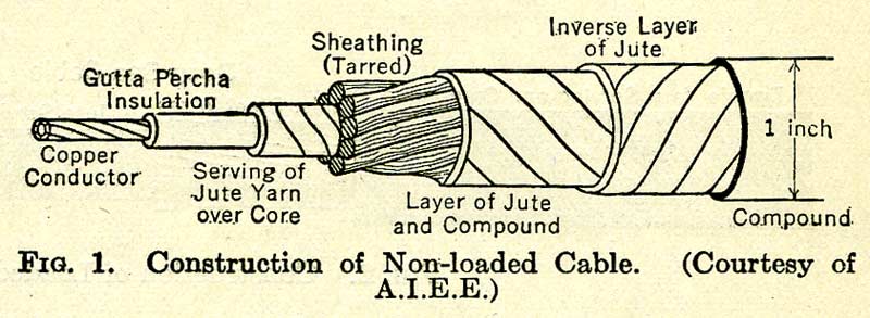
Submarine telegraph cables are specially insulated and armored conductors that are laid on ocean bottoms to provide wire communication between points separated by great expanses of water. Non-loaded cables usually consist of a single copper conductor which may be either solid, stranded, or a combination of both, to afford greater flexibility, surrounded by a thick gutta‑percha insulation. This insulated conductor or “core” is protected from mechanical injury by several layers of tanned jute and a layer of steel armor wire as shown in Fig. 1.
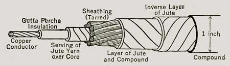
Fig. 1. Construction of Non-loaded Cable |
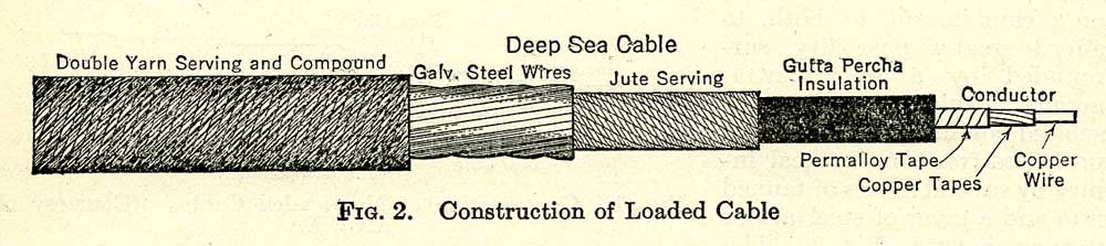
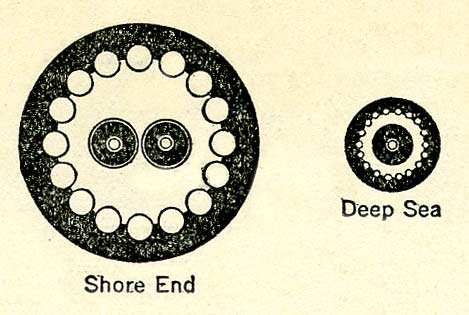
The completed diameter of cables laid in deep water is about ¾ in. to 1½ in., depending upon the size of conductor and thickness of gutta-percha. Sections of cable laid in shallow water are built up with additional layers of armor wire and jute to a diameter of as much as 4 in. to provide additional mechanical protection against abrasion due to wave action and injury from ship’s anchors. Loaded cables, Fig. 2, are of similar construction except that the central conductor is surrounded with a thin spirally wound tape or wire of an alloy having high magnetic permeability at very low magnetizing forces. The addition of this loading material effects a marked reduction in attenuation of the signaling currents at higher speeds and diminishes signal distortion. The second conductor shown in the section of the shore end is used to carry the receiving ground connections out to deep water in order to obtain greater freedom from disturbances created by power circuits and natural causes.
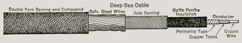
Fig. 2. Construction of Loaded Cable
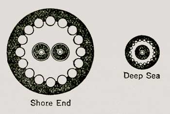
|
The electrical and mechanical properties of types of core frequently used are shown in Tables 1 and 2.
| Table 1. Some Properties of Frequently Used Types of Non-loaded Cables |
Weight, Pounds per
Nautical Mile
|
Diameter of
Conductor,
Mils |
Diameter over
Gutta-percha,
Mils |
Resistance,
Ohms per
Nautical Mile
at 75 Deg Fahr |
Capacity,
Microfarad
per Nautical
Mile |
| Copper |
Gutta-percha |
| 70 |
120 |
70 |
252 |
16.90 |
0.272 |
| 107 |
120 |
86 |
258 |
11.05 |
0.316 |
| 107 |
166 |
86 |
298 |
11.05 |
0.280 |
| 130 |
130 |
95 |
270 |
9.10 |
0.334 |
| 140 |
140 |
99 |
280 |
8.45 |
0.335 |
| 160 |
150 |
106 |
291 |
7.40 |
0.345 |
| 180 |
160 |
112 |
302 |
6.58 |
0.351 |
| 200 |
180 |
114 |
318 |
5.92 |
0.339 |
| 225 |
225 |
124 |
354 |
5.25 |
0.332 |
| 275 |
225 |
138 |
360 |
4.30 |
0.363 |
| 350 |
300 |
151 |
412 |
3.38 |
0.347 |
| 500 |
315 |
180 |
432 |
2.32 |
0.398 |
| 650 |
400 |
203 |
487 |
1.82 |
0.398 |
| 700 |
360 |
211 |
470 |
1.69 |
0.435 |
|
| Table 2. Some Properties of Frequently Used Types of Loaded Cables |
Weight, Pounds per
Nautical Mile |
Diameter in Mils—over |
Resistance,
Ohms per
Nautical
Mile at 75
Deg Fahr |
Capacity,
Microfarad
per
Nautical
Mile |
Inductance,
Millihenries
per
Nautical
Mile |
| Copper |
Gutta-
percha |
Loading
Material |
Con-
ductor |
Load-
ing |
Gutta-
percha |
| 573 |
387 |
72 |
180 |
192 |
480 |
2.09 |
0.370 |
63 |
| 517 |
355 |
61 |
171 |
182 |
430 |
2.31 |
0.375 |
86 |
| 255 |
252 |
43 |
121 |
132 |
360 |
4.65 |
0.318 |
140 |
| *277 |
258 |
73 |
126 |
148 |
375 |
4.28 |
0.340 |
170 |
| *605 |
370 |
104 |
182 |
202 |
...... |
1.97 |
0.393 |
118 |
| *Approximate values. |
|
OPERATION OF NON-LOADED CABLES
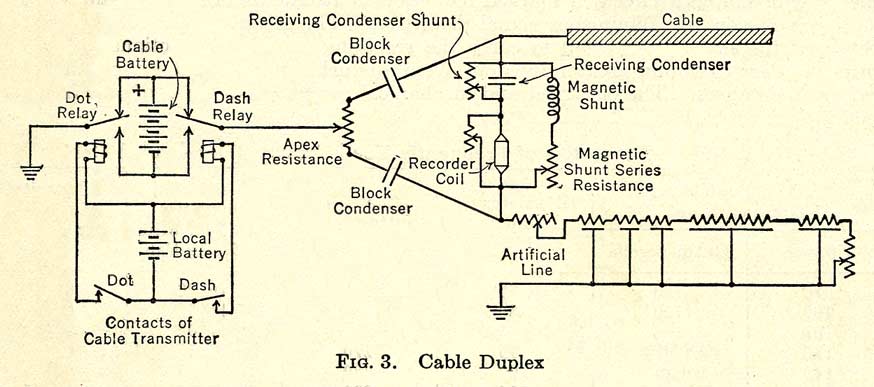
The high resistance and electrostatic capacity of long non-loaded submarine cables (longest about 3500 nautical miles) distort and attenuate the signaling impulses to such extent as to preclude the use of ordinary land line methods of operation. Such cables are usually duplexed, using the modified form of bridge duplex, shown schematically in Fig 3, in which the usual bridge inductance coil is replaced by condensers which offer high impedance to slowly varying currents due to differences in potential of the earth connections at the two ends of the cable. Satisfactory operation requires that the current in the receiving arm of the bridge, due to imperfect balance, shall not exceed one-sixth of the received signaling currents. This necessitates maintaining a balance accurate to about 1 part in 10,000 or better between the cable and the artificial line.
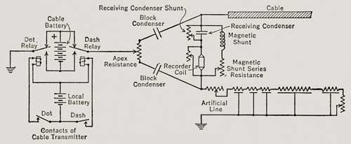
Fig. 3. Cable Duplex |
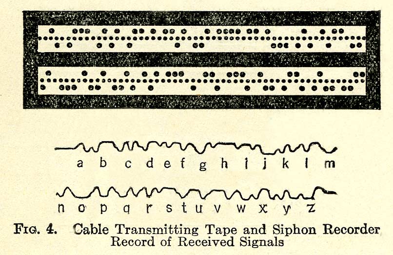
Signals in the cable Morse code are transmitted from a perforated tape, Fig. 4, by a transmitter and group of relays, arranged to apply either positive or negative battery or ground to the apex of the bridge. In many cases each signaling impulse is immediately followed by a shorter period during which the cable is grounded to improve the shape of the received signals. This is called “curbing,” and such signals are referred to as “curbed signals.”
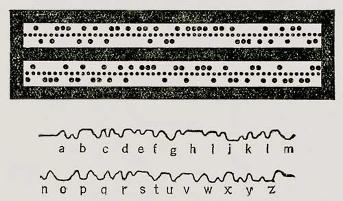
Fig. 4. Cable Transmitting Tape and
Siphon
Recorder Record of Received Signals |
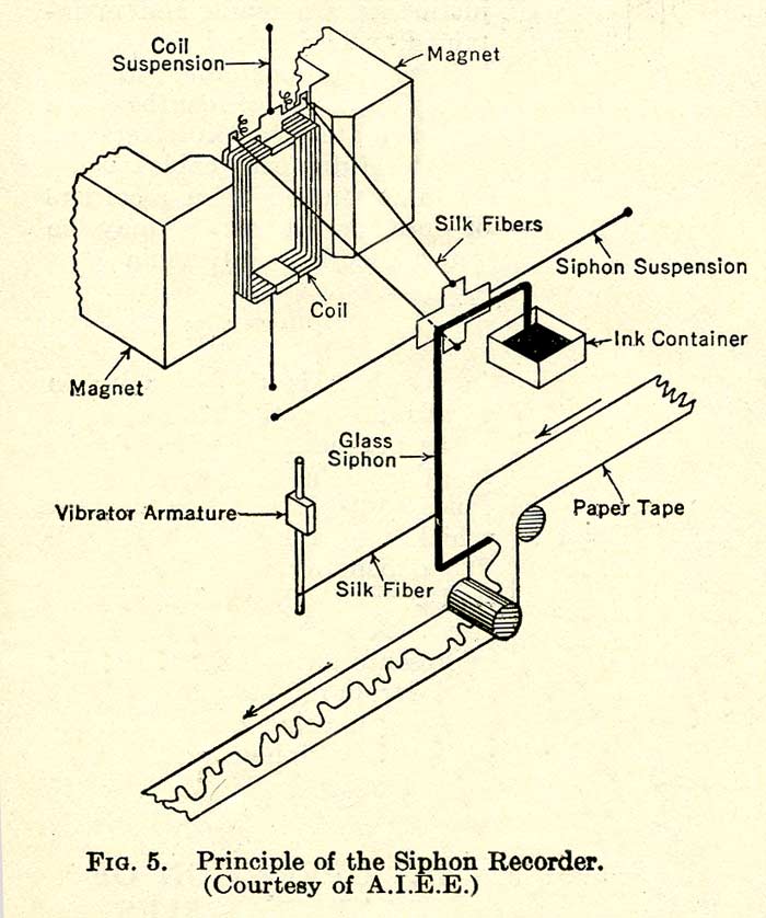
Received signals for manual translation are recorded on a moving paper tape by a siphon recorder. This is essentially a d’Arsonval galvanometer in which the movements of the coil are mechanically transmitted to a small-bore (0.010-in) glass siphon tube that acts as an ink writing pen and traces the signals on a paper tape moving beneath the siphon point; see Fig. 5. The writing point of the siphon is rapidly vibrated in a plane perpendicular to the plane of the record tape by means of an electromagnetic vibrator which is connected with the siphon by a slender silk fiber. This is necessary to reduce the friction between siphon and paper to a minimum and results in the record being a series of closely spaced dots instead of a continuous line. The distorted received signals, which would otherwise be difficult to interpret, are “shaped” or “corrected” by proper adjustment of the shunted receiving condenser and the magnetic shunt, or inductance, and its associated series resistance shown in Fig. 3, and by means of altering the natural frequency of oscillation of the moving system of the recorder. The received signals, after being thus shaped, appear on the siphon recorder tape as shown in Fig. 4.
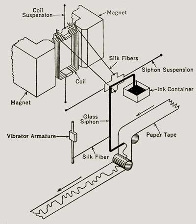
Fig. 5. Principle of the
Siphon
Recorder |
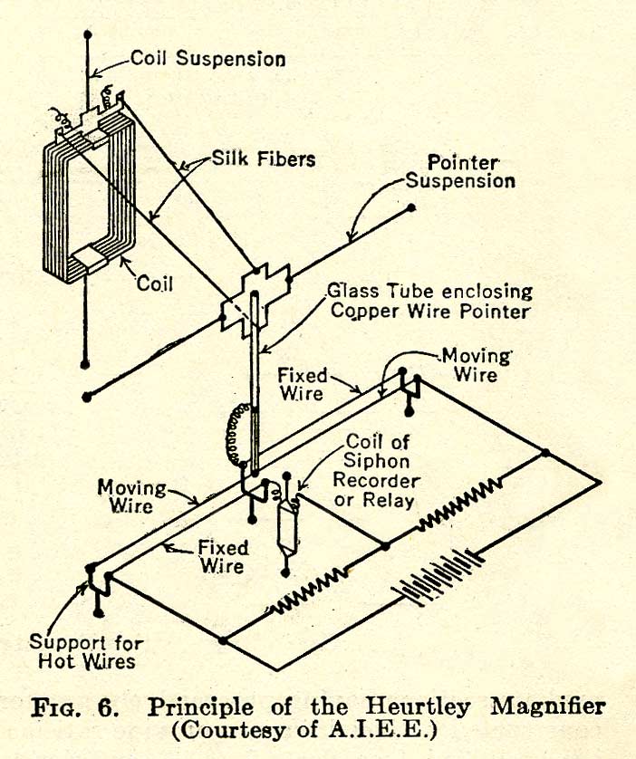
The received signals on long non-loaded cables operating at commercially economical speeds are generally too feeble to operate a siphon recorder or relay directly, and some form of amplification becomes necessary. Mechanical amplifiers commonly designated “magnifiers” are used for the purpose. A frequently used type, shown schematically in Fig. 6, is known as the Heurtley magnifier. It employs a moving coil which swings two 0.0003-in.-diameter platinum wires into and out of close proximity to two similar stationary wires, all of which are electrically heated. These two pairs of wires form two arms of a balanced Wheatstone bridge which has a battery connected across one diagonal and a siphon recorder or relay connected across the other. As the coil moves in response to a signal of one polarity one of the moving wires is brought nearer to its associated stationary wire, which raises the temperature of both wires and consequently increases their electrical resistance, while the separation between the other moving wire and its associated heated wire is increased, thereby lowering their temperature and electrical resistance. This unbalances the bridge and causes current to flow in one direction through the siphon recorder or relay. Movement of the moving wires in the other direction in response to a signal of opposite Polarity also unbalances the bridge, but in a way to reverse the direction of current in the siphon recorder.
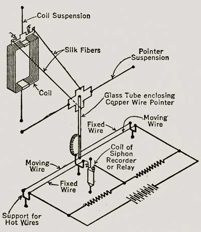
Fig. 6. Principle of Heurtley Magnifier |
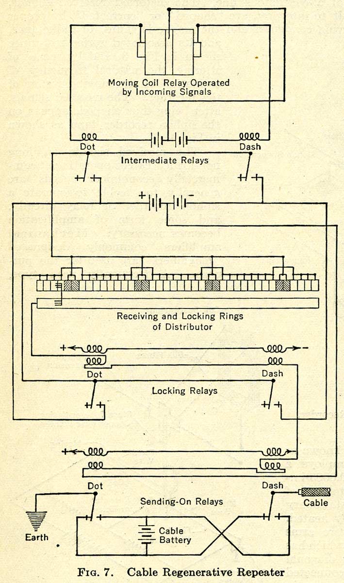
Repeaters for joining two sections of non-loaded cable are usually of the regenerative type, shown in Fig. 7 and are similar in principle of operation to the regenerative repeaters used in land lines. The received signals are “magnified” or “amplified” and used to control a moving-coil relay similar in construction to a siphon recorder in which the siphon is replaced by a delicate contact “tongue” which moves between two other contacts that are continuously vibrated or moved to reduce friction. This relay controls the operation of two more rugged relays which repeat the signals into the regenerator circuits.
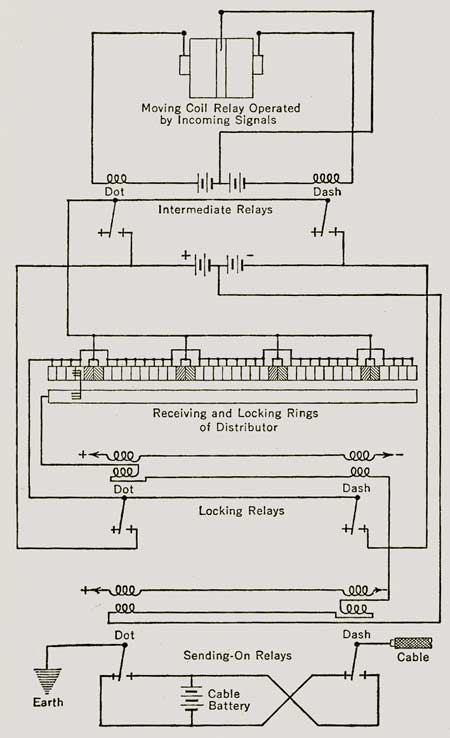
Fig. 7. Cable Regenerative Repeater |
Printers for non-loaded cables are similar to the multiplex printers employed on land lines with certain modifications which are necessitated by the different types of code used.
The operating speed of a non-loaded cable is determined by the length and construction of the cable itself, by the nature and magnitude of any extraneous interference, and by the kind of apparatus used and the precision with which the apparatus and balance adjustments are made and maintained. The speed is almost inversely proportional to the square of the cable length. The approximate speed in letters per minute of duplexed cables, using magnifiers and siphon recorders or moving-coil relays, may be determined by the formula
Speed lpm = K/krl²
in which k is the capacity in farads and r the resistance in ohms per nautical mile, l is the length of the cable in nautical miles, and K is the speed constant which varies between 550 and 700 depending upon the length and type of cable and apparatus used. A speed constant of 660 represents an average value for cables from 1000 to 2000 nautical miles long, using Heurtley magnifiers and siphon recorders or relays.
OPERATION OF LOADED CABLES
Cables in which the loading is distributed uniformly from end to end have not thus far been successfully duplexed and are, therefore, operated simplex, or in only one direction at a time. Taper loaded cables, which comprise two non-loaded terminal sections joined to a main loaded portion through several intermediate sections having progressively greater inductance, may be balanced by specially constructed artificial lines to provide satisfactory duplex operation. The received signals are amplified sufficiently by a vacuum-tube amplifier to control a modified form of multiplex printing system. The channel speed is usually between 250 and 300 letters per minute, and the number of channels varies between 2 and 8 depending upon the construction of the cable. One uniformly loaded cable, approximately 2300 nautical miles in length, operates at 65 cycles per second and provides 5 one-way channels, each operating at 312 letters per minute. Another cable consisting of two cable sections, respectively 1344 and 2023 nautical miles long, and two land line terminal sections joined by 3 intermediate regenerative repeaters, operates simplex, or in one direction at a time, at a speed of 100 cycles per second which provides eight 300-letter‑per-minute channels. One duplexed taper loaded cable 1341 nautical miles long is capable of being operated at a speed of 70 cycles per second in both directions simultaneously with a 4-channel multiplex system.
PICTURE TRANSMISSION
A special method of transmitting pictures, known as the Bartlane System, is used on submarine cables where the comparatively low transmission frequencies preclude the economical use of conventional facsimile or picture-transmission methods. This system provides for the transmission of black and white and a predetermined number of intermediate tone or shade values. The picture to be transmitted is scanned by a photoelectric apparatus which selects the shade value most nearly corresponding to the shade of each successively exposed area of the picture, and automatically perforates a transmitting tape with a code combination representing the selected shade. The perforated tape is passed through the regular transmitter on the cable in the same way as any ordinary transmitting tape. A corresponding perforated tape, prepared by a receiving perforator, is used to operate the picture-reproducing apparatus. Each square inch of picture surface is broken up by the scanning apparatus into about 3600 squares 1/60 in. on a side. As each of these small areas is transmitted separately over the cable it requires about 2¼ min to transmit a square inch of picture surface on a circuit operating at 1500 letters per minute.
POWER AND MAINTENANCE
Power for submarine cable transmission is generally supplied by storage batteries which rarely exceed 100 volts. Storage batteries are also used to supply current for operating the local circuits of magnifiers, moving-coil relays, and siphon recorders, while generators are used for supplying energy to the local circuits of printers and associated apparatus.
Faults in submarine cables are located by means of insulation resistance, capacitance, and conductor resistance measurements made with a special form of bridge and a sensitive galvanometer in a manner which is similar in principle to the tests made in locating faults on land lines.
BIBLIOGRAPHY
General References:
Theory of the Submarine Telegraph and Telephone Cable, H.W. Malcolm. Benn Brothers (The Electrician), London, 1917.
Submarine Telegraphy, Italo de Giuli. Sir Isaac Pitman and Sons, London, 1932.
Special References:
Submarine cable telegraphy, J.W. Milnor. Trans. A.I.E.E., Vol. 41, 1922.
The Newfoundland-Azores high speed duplex cable, J.W. Milnor and G.A. Randall. Trans. A.I.E.E., Vol. 50, 1931.
Printing telegraphs on non-loaded ocean cables, H. Angel. Trans. A.I.E.E., Vol. 46, 1927.
Direct printing over long non-loaded submarine telegraph cables, M.H. Woodward and A.F. Connery. Trans. A.I.E.E., Vol. 51, 1932.
The application of vacuum tube amplifiers to submarine telegraph cables, A.M. Curtis. Bell System Tech. J., Vol. 6, 1927.
Automatic printing equipment for long loaded submarine telegraph cables, A.A. Clokey. Bell System Tech. J., Vol. 6, 1927.
The loaded submarine telegraph cable, O.E. Buckley. Bell System Tech. J. , Vol. 4, 1925.
A non-rotary regenerative telegraph repeater, A.F. Connery, Trans. A.I.E.E., Vol. 48, 1927.
Modern photo telegraphy, R.C. Walker. Wireless World, Vol. 30, 1932.
Allison A. Clokey’s US Patents:
| Patent No. |
Title |
Filing Date |
Issue Date |
Inventor |
Assignee |
| 1164069 |
Call-Box |
Jun 23, 1915 |
Dec 14, 1915 |
A. Clokey
(Jersey City) |
The Western Union Telegraph Company |
| 1196335 |
Recorder |
Feb 2, 1915 |
Aug 29, 1916 |
Allison A. Clokey |
The Western Union Telegraph Company |
| 1224359 |
Contact Arrangement For Call Boxes And Other Transmitters |
Dec 6, 1916 |
Dec 14, 1917 |
Allison A. Clokey |
The Western Union Telegraph Company |
| 1480243 |
Signaling System |
Nov 5, 1921 |
Jan 8, 1924 |
Allison A. Clokey
(Rutherford) |
Western Electric Company |
| 1521870 |
Telegraph System |
Dec 1, 1921 |
Jan 6, 1925 |
Allison A. Clokey |
Western Electric Company |
| 1522865 |
Signaling System |
Nov 29, 1921 |
Jan 13, 1925 |
Allison A. Clokey |
Western Electric Company |
| 1549907 |
Telegraphy |
Nov 11, 1920 |
Aug 18, 1925 |
Allison A. Clokey |
Western Electric Company |
| 1557420 |
Signaling System |
Jun 18, 1920 |
Oct 13, 1925 |
Allison A. Clokey |
Western Electric Company |
| 1570460 |
Telegraph System |
Oct 15, 1920 |
Jan 19, 1926 |
Allison A. Clokey |
Western Electric Company |
| 1586878 |
Telegraph System |
Nov 2, 1922 |
Jun 1, 1926 |
Allison A. Clokey |
Western Electric Company |
| 1586894 |
Submarine-Cable |
May 12, 1922 |
Jun 1, 1926 |
John J. Gilbert and Allison A. Clokey |
Western Electric Company |
| 1586965 |
Telegraph System |
May 12, 1920 |
Jun 1, 1926 |
Allison Andrew Clokey |
Western Electric Company |
| 1586966 |
Synchronizing System |
Jun 25, 1924 |
Jun 1, 1926 |
Allison A. Clokey |
Western Electric Company |
| 1588527 |
Signaling System |
Feb 18, 1924 |
Jun 15, 1926 |
Allison A. Clokey |
Western Electric Company |
| 1601940 |
Telegraph System |
Oct 3, 1922 |
Oct 5, 1926 |
Allison A. Clokey |
Western Electric Company |
| 1601941 |
Submarine Telegraph System |
Oct 4, 1922 |
Oct 5, 1928 |
Allison A. Clokey |
Western Electric Company |
| 1601942 |
Telegraph System |
Jun 30, 1923 |
Oct 5, 1926 |
Allison A. Clokey |
Western Electric Company |
| 1609060 |
Recording Instrument |
Jan 19, 1924 |
Nov 30, 1926 |
Allison A. Clokey |
None |
| 1616607 |
Signaling System |
Dec 15, 1923 |
Feb 8, 1927 |
Allison A. Clokey |
Western Electric Company |
| 1624393 |
Telegraph System |
May 29, 1926 |
Apr 12, 1927 |
Allison A. Clokey |
Bell Telephone Laboratories |
| 1666195 |
Duplex Telegraph System |
May 13, 1927 |
Apr 17, 1928 |
Allison A. Clokey |
Bell Telephone Laboratories |
| 1695040 |
Multiplex Telegraph System |
Jul 29, 1926 |
Dec 11, 1928 |
Allison A. Clokey |
Bell Telephone Laboratories |
| 1717094 |
Vibration Device |
Dec 29, 1923 |
Jun 11, 1929 |
Allison A. Clokey |
Western Electric Company |
| 1717095 |
Potential-Limiting Device |
Mar 22, 1926 |
Jun 11, 1929 |
Allison A. Clokey |
Bell Telephone Laboratories |
| 1742899 |
Synchronous Telegraphy |
Jan 5, 1928 |
Jan 7, 1930 |
Allison A. Clokey |
Bell Telephone Laboratories |
| 1753331 |
Constant-Speed Drive |
May 29, 1926 |
Apr 8, 1930 |
Allison A. Clokey |
Bell Telephone Laboratories |
| 1779462 |
Telegraph System |
Dec 26, 1928 |
Oct 28, 1930 |
Allison Andrew Clokey |
International Standard Electric Corporation |
| 1799214 |
Submarine Telegraph System |
Mar 7, 1929 |
Apr 7, 1931 |
Allison A. Clokey |
Bell Telephone Laboratories |
| 1813913 |
Rotary Distributor |
Dec 7, 1923 |
Jul 14, 1931 |
Allison A. Clokey and William A. Knoop |
Bell Telephone Laboratories |
| 1823088 |
Submarine Cable Repeating System |
Sep 10, 1928 |
Sep 15, 1931 |
Allison A. Clokey |
Bell Telephone Laboratories |
| 1898760 |
Means For Increasing Visibility Of Stock Quotation Boards |
Mar 4, 1931 |
Feb 21, 1933 |
Allison A. Clokey |
International Communications Laboratories |
| 1898761 |
Step-By-Step Transmitter |
Oct 23, 1931 |
Feb 21, 1933 |
Allison A. Clokey |
International Communications Laboratories |
| 1898762 |
Selecting System Using A Single Magnet |
Oct 31, 1931 |
Feb 21, 1933 |
Allison A. Clokey |
International Communications Laboratories |
| 1920153 |
Call Box Register Circuit |
Jul 17, 1930 |
Jul 25, 1933 |
Allison A. Clokey |
International Communications Laboratories |
| 1927699 |
Telegraph System |
Aug 31, 1932 |
Sep 19, 1933 |
Allison A. Clokey and Marion H. Woodward |
International Communications Laboratories |
| 1964031 |
Call Circuit Recorder |
Aug 14, 1930 |
Jun 26, 1934 |
Allison A. Clokey |
International Communications Laboratories |
| 2137603 |
Stock Quotation Board System |
Nov 13, 1930 |
Nov 22, 1938 |
Allison A. Clokey and Gilbert S. Vername |
International Standard Electric Corporation |
| 2193581 |
Mixing Valve |
Nov 5, 1935 |
Mar 12, 1940 |
Allison A. Clokey |
None |
|