INTRODUCTION
When preparing the specifications for this new Anglo-French cable, it was decided that the general design of the new telephone cable in respect of the copper and the dielectric should be exactly similar to the type already in use, which it was known would provide telephonic transmission of a certain quality, and that the improvement desired could be obtained by the contractors either by means of “continuous” loading or “coil” loading, the Department simply stipulating in the specification that the attenuation constant should not exceed a certain definite value. The main reason for this was that if it had been discovered after the cable had been laid that coils introduced effects not foreseen, the coils could easily have been cut out at a small cost and the Department would still have had a cable as good as the existing one. ( It is known that under certain conditions of design in the relation of the weight of gutta percha to that of copper per knot, an effect is created referred to colloquially as “drumminess.” “Drumminess” is a property which causes speech to be muffled, and therefore renders it less distinct. In an unloaded circuit “drumminess” is generally unmistakable, when the ratio K/R per mile is equal to 0.003. [K = microfarads, and R = Ohms]. The greater this ratio the more marked is the “drumminess.”
Selected firms were asked to tender for the additional cable to be provided by the British Administration. No tenders were received for the “continuous” type of loading, but three tenders were received for the “coil” type of loading. In each case the method of providing the increased inductance was different. In one case the mechanical aspect of the question had been very carefully gone into, and the device proposed for increasing the inductance was certainly ingenious, but this type of cable did not promise to he quite so efficient electrically as that which was finally selected; the question of cost was also a ruling factor in the situation.
The features of the device for loading in the accepted tender are as follows:‑
The two double coils required for the four conductors of the cable, each coil being of slightly less than 6 ohms resistance and having an inductance of 0.10 henry at 750 periods per second, are inserted at intervals of 1 knot (1.153 miles), but the two coils nearest the ends of the cable are inserted at a distance of only half a knot from the terminal apparatus, as experiments have shown that in this arrangement reflection losses are considerably reduced. Each double coil consists of two windings on the same iron core, and one winding is connected in series with each conductor. By this means the gradual change in permeability in the iron core due to ageing will not affect the balance in the two limbs of the telephone circuit. Each coil is protected with a sheet of metal foil in order to exclude all possibility of the silk cowering of the wires of the coils absorbing moisture from the cylindrical envelope of gutta percha in which they are contained. The cores of the cable are connected to the envelope at its two ends by tapered solid gutta percha joints. The diameter at the centre of the envelope is 3 in., and at the cores where the joints terminate 1 in. An annular rubber distance-piece is inserted between the two coils of a set to give greater flexibility. The total length of the joint is 30.75 in. As the diameter of the cable at the points where the coils are inserted is increased, a larger number of sheathing wires are required at those points than over the conductors alone. This difficulty is ingeniously overcome by starting a second layer of sheathing wires over the cores, about 27 ft. from the centre of the coil envelope and gradually working them into a single layer with those over the bulge. Finally they are terminated as a second layer again over the cores at a distance of about 27 ft. from the centre of the coil envelope. The method adopted in inserting the coils (Patent Specification No. 5,547 March, 1907) will perhaps be understood from the diagrams.
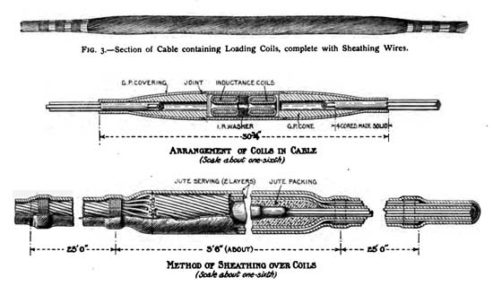
Diagrams showing the lump-loading of the cable
("non-continuous” or “coil” loading system) |
It will be recognised that the mechanical problem in connection with this type of cable was more difficult to solve than the electrical problem, as it was necessary that the part of the cable containing the coils should be so designed that it could be paid over the sheaves of the cable-ship without any risk of damage to the coils themselves. However, I am glad to say that the manufacturers succeeded in solving this problem in a most satisfactory manner.
In dealing with the maintenance of “coil” loaded cables after they have been laid, the degree of importance to be attached to the uniform spacing of the coils has to be considered. In repairing cables, intermediate lengths have to be inserted at times, but fortunately if repairs of this character have to be effected in the “coil” loaded cable, no noticeable impairment in the quality of the speech will result if the coil spacing is disturbed to an extent not exceeding 5 per cent. on either side of the best location from the theoretical point of view. It has been found that when physical conditions impose a variation of not more than 50 per cent. of the spacing for a single coil, no appreciable impairment in the quality of the speech will result provided thedeficiency in loading is made up within the next ten loading sections.
The investigations that had been made left little doubt concerning the balance of advantages in favour of the “coil” loaded type of cable from the electrical standpoint, but as the expenditure involved was very great, and as it was felt that the main difficulty in connection with this type of cable would be in safely laying the cable at the bottom of the sea, it was considered that special precautions were necessary to ensure that the responsibility for any defects that might be disclosed after it had been laid, should be definitely traced to the responsible party. To afford the necessary protection to the Department, it seemed desirable to stipulate in the specification that the manufacturers of the cable should also undertake to lay it, and to hand it over in situ. This course was approved by the Postmaster-General, and the invitations to tender were issued on these lines. The conditions were accepted by Messrs. Siemens Bros. & Co., who were the successful tenderers.
DESCRIPTION OF THE LAYING OF THE CABLE.
Mr. W. Dieselhorst was entrusted by Messrs. Siemens Bros. with the actual operation of laying the cable, and Mr. F. Pollard, Submarine Superintendent, Dover, was detailed to watch the interests of the Post Office.
The cable ship Faraday was employed for the purpose of laying the cable. As a precautionary measure, the ordinary paying-out drum had been replaced by one of larger diameter, and fleeting-knives were also provided in order to prevent the cable from over-riding. The new drum was 8 ft. in diameter, and 3o in. wide, and three fleeting-knives were fitted side by side to this rather wide drum to prevent any undue pressure on the loading coils, which would be caused if two turns on the drum were fleeted by one knife only. It was further decided to pay the cable out without passing it under the dynamometer wheel as is usually the case where deep-water cables are concerned. All bends were avoided by letting the lead from the tank go on to the upper part of the drum, and an open wood trough was fixed from the cable tank to the drum to support and protect the cable between these points. Since the upper part of the drum is nearly in line with the stern sheave there was no extra bending of the cable over any intermediate supporting sheaves after it had left the drum. The stern sheave on board the Faraday, which has a diameter of 4 ft., can be swung out at will to any angle, and this was found to be exceedingly serviceable when turning the ship round at right angles near Abbot's Cliff, and again when the French coast was reached.

Diagram showing Dimensions of C.S. Faraday's Paying-out Drum with Fleeting-knives. |

Easing a Loading Coil over the Sheaves. |
The cable was paid into the Faraday's tank on the 2nd and 3rd of May, 1910, and the ship left Woolwich on the 4th with the official representative of the Post Office on board. A large party of gentlemen—from this country and Germany—especially interested in telephone enterprise embarked on the Faraday as guests of Messrs. Siemens. Operations were commenced at 5 a.m on May 5, 1910, by dropping a buoy, to which the shore end was attached, overboard about ½ mile from the South Eastern Railway Company's retaining wall south of the tunnel works. For some distance the cable was laid parallel to the British coast, until a point was reached opposite the landing-point, when the ship's bow was turned towards the French coast.
Preparations had been made by the British Administration to assist the Faraday in keeping her course, and for this purpose buoys had been placed at intervals by H.M.T.S. Monarch, the positions of which were recorded on a chart supplied to the contractors. The importance of these preliminary arrangements cannot be exaggerated. The English Channel is becoming very congested as regards cable routes, and in order to facilitate the maintenance of new telephone cables some alterations in the routes of old cables had been effected on the English coast, so as to avoid the laying of the new cable over old ones—these alterations are shown in the chart. This chart does not by any means show the whole of the cross-channel cables at this point, there being nine cables in all.
 |
The day being fairly clear and the sea smooth, the Faraday was easily able to follow the line of buoys, and the laying of the cable went off without a hitch, but a brisk wind sprung up late in the afternoon, and the Faraday had a somewhat rough passage back. It was not possible for the Faraday to approach nearer than 1½ miles to the French landing-place, as the coast shelves out very gradually. Therefore, when the ship was about that distance from the coast, the course was altered, and the remaining portion of cable paid overboard approximately parallel to the coast.
The landing of the shore ends was undertaken by Mr. F. Pollard, Submarine Superintendent, on May 18, 1910. H.M.T.S. Alert was employed for this purpose, and the work commenced at 5 a.m. The shore end on the English coast was first picked up, and the cable coiled into the ship's forward tank. The Alert then steamed in as close to the shore as her draught would allow and anchored. A raft was made, and the shore end paid out on to it. The raft was then towed ashore by means of a warp rope, the cable being paid out into the water. This work was completed at 11 a.m., and the Alert at once proceeded to the French coast, where the section of cable parallel to the coast was picked up. When the tide permitted, the ship steamed in towards the French shore paying out the cable. A short length provided in excess of the actual length required to reach the shore was cut off and the remainder of the cable was paid overboard at a distance of about 350 yards from the cable hut. When the tide receded this section of the cable was uncovered, and it was possible to carry the end to the cable hut.
Since the bow sheaves of the Alert are only 2½ ft. in diameter, it was thought advisable to take special precautions in picking up, and taking the portions of the cable containing the loading coils on board, and again in paying them out, so as to ensure that the loading coils should not suffer any damage. For this reason loading coil sections were not allowed to ride on the bow sheaves, but tackle was fixed to a derrick, and the coils were carefully lifted over the sheaves. However, in the case of the coils in the section of the cable in excess of that required for present needs, the opportunity was seized to ascertain whether the coils would be injured if allowed to pass over the Alert's sheaves in the absence of the precautions referred to. This portion of the cable therefore, was hauled aboard in the usual manner, and a speech test was then made on the four conductors of the cable (the ends being looped at the English end) to ascertain whether any damage had resulted. No injury was disclosed in the test; in fact, everything appeared in the best of order.
The cable has been under continuous observation since it was laid and a large number of tests have been carried out. It has fortunately been possible to obtain independent testimony on the question of the increase in the range, and in the improvement in the quality of speech transmitted by means of the loaded cable as compared with a similar cable unloaded. Speech tests were made in July last by Messrs. W. R. Cooper, W. Duddell, F.R.S., W. Judd, and J. E. Kingsbury, and the results are interesting. The cable was looped at the French end (Cape Grisnez), and the English ends were connected to two telephone sets—one installed in the cable but at Abbot's Cliff, and the other in the coastguard look-out shelter some 100 ft. distant. Graduated artificial cables were provided so that the listener at the cable-hut could insert various values of the “standard” cable into the circuit, until his own limit of satisfactory audibility was reached. It was possible to insert the “standard” cable values equally at the two ends of the cable (i.e., so as to form a symmetrical circuit in relation to the submarine cable), or unequally, as desired.
The mean gain by the use of the new cable is therefore 17 miles of “standard” cable for the standard of audibility accepted as commercial by the four observers named. When the cables were alone in circuit some of the observers noticed that in the case of the new cable there was a distinct improvement in the quality of the speech as compared with the old cable.
The employment of unloaded 800-lb. copper aerial conductors such as are in use for the most important long-distance trunk circuits in this country, will render it possible for very satisfactory conversations to take place from call-boxes between centres in England and on the Continent when the added distances from the ends of the cable do not exceed 1,700 miles: that is to say, with land-lines of this description well-maintained conversations between London and Astrakhan on the Caspian Sea would be possible.
CONCLUSION
Although great improvement in speech transmission has resulted from this latest type of cable, yet the new Anglo-French cable cannot by any means be regarded as the last word on submarine telephone cables. An attempt has been made in this paper to place on record some of the steps taken in developing the art of long-distance telephony, but many problems remain to be solved, and they do not appear to be of a character likely to yield a ready answer to those seeking their solution. As in the past, the co-operation of the mathematician, physicist, engineer, and manufacturer are still needed if an announcement is to be made in this theatre twenty years hence that the progress in the art of telephony has resulted in an increase of efficiency comparable with that which has been achieved during the past twenty years, and which it has been my pleasure to record here to-night.
The practical engineer recognises fully how much he is indebted to the mathematical investigations of Messrs. Heaviside, Pupin, Perry, Kennelly, and others, in respect of the progress made in the past. There are to-day a number of earnest workers, both in this country and in foreign lands, who are sparing no efforts to render possible the transmission of speech from any one point of the habitable globe to any other. In America, Mr. J.J. Carty, of the American Telephone and Telegraph Company, is engaged in solving the problem of putting the towns of the East Coast of the United States of America into communication with the towns on the West Coast of that great continent. Recently, at Paris, he stated that he hoped to establish satisfactory communication between New York and Denver (distance, 1,700 miles) during the autumn of this year. Experimental investigations are being carried out by, amongst others, M. Devaux-Charbonnel in France, Drs. Breisig and Ebeling in Germany, M. Bela Gati in Hungary, and here in our midst Mr. Gill and his able staff of assistants are vying with Mr. H.R. Kempe, the electrician, and the capable staff engaged on this work at the General Post Office.


