History of the Atlantic Cable & Undersea Communications
from the first submarine cable of 1850 to the worldwide fiber optic network
|
History of the Atlantic Cable & Undersea Communications |
|
Salient Features In Cable Design Since 1850 |
|
Introduction: In 1950, Submarine Cables Ltd published a 20-page booklet titled Submarine Telegraph Cable Centenary, commemorating the 100th anniversary of the laying of the first submarine cable from Dover to Calais in 1850. As well as a brief history of significant events in the industry, the booklet included a table of notable technical achievements in cable design. Ten years later, in 1960, the company produced another booklet, titled One Hundred and Ten Years of Undersea Telecommunications. This updated the technical section of the first publication and added the advances of the 1950s, the most significant one being the introduction of repeaters, which made feasible long-distance undersea telephone cables across the Atlantic and elsewhere. The introduction from the 1950 booklet and the two sets of technical data are reproduced below, providing an interesting insight into the design changes which improved the performance and longevity of submarine cables from 1850 to 1959.
|
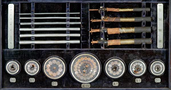
SALIENT FEATURES IN CABLE DESIGN SINCE 1850 The following information illustrates the various milestones which have marked the development of Submarine Telegraph and Telephone Cables. In order to appreciate the symbols used, the following explanation is made:- In early days, most of the progress made in cable design centred round the type and weight of armouring. Iron wires, drawn to one of the standard sizes then available, were used, and the cable armouring was designated by two numbers separated by a stroke (e.g., 12/4). These indicated respectively the number of wires wrapped simultaneously round the cable and the gauge number of the wire. Where double armouring was used, this was expressed by two such symbols (e.g., 14/1, 10/6). Heavy armouring (not necessarily double armouring) is always used for cables near the shore where rocks and tides are encountered, but light armour is used for deep sea work. Armour of intermediate weight is used for “intermediate” conditions of depth. In due course heavily armoured cable (i.e., carrying No. 2 wires or larger) became known as Type A. Intermediate armour (i.e., Nos. 4 or 6 wires) was known as Type B and light armour (i.e., wires of No. 11 to No. 14 gauge) was known as Type C and finally as Type D.
A hundred years ago, the steel industry could not give cable manufacturers armour wire of high tensile qualities, but in present times deep sea cable is always armoured with wires having a tensile strength of from 65 to 95 tons per square inch, while low tensile (soft iron) wire of large section having a tensile strength of 35 tons per square inch is used for shallow water cables. In due course, some cables were sheathed with armour wires each of which was protected with a fabric tape wrapping impregnated with bituminous compound. This was to minimise corrosion of the wires, and such armouring was referred to as “Taped Wires”. Helical wrappings of textile material were called servings. When describing the size of the conductor and insulation, it is now customary to quote two numbers separated by a stroke (e.g., Core 130/130), the two numbers denoting the weights of the copper conductor and the insulation respectively, in lbs. per nautical mile (2,029 yards). It will be noted that, in recent years, the main developments have been in transmission characteristics rather than in cable armouring. |
|
| Date | Cable Made For | Location | Length Nautical Miles |
Types of Armour Used For | Salient Features of Design to be Noted | ||
| Shallow Water |
Intermediate Depths |
Deep Sea |
|||||
| 1850 | Brett & Co. | Calais - Dover | 25 | unarmoured | Gutta percha covered wire only. Conductor comprised of solid copper. | ||
| 1851 | Crampton | Calais - Dover | 25 | 10/1 | |||
| 1856 | Atlantic Telegraph Co. | Newfoundland - Cape Breton | 85 | 12/4 | 12/9 | First time stranded conductor used. Also heavier armour used at shore ends. | |
| 1859 | Isle of Man Telegraph Co. | Whitehaven - Isle of Man | 36 | Outer servings used for the first time, and adopted subsequently for all types except on stranded (shore end) armouring. It was used on Type C having served wires. In this case its use was to keep broken wires bound down. The use of so much fibrous material lead to the development of “Bread and Butter” type cable. | |||
| 1860 | French Govt. | France - Algiers | 450 | 10/00 called Type A | 10/5 called Type | 10/14 called Type C each wire Hemp served |
First time an “intermediate” armour used. First time hemp protection of individual wires used. First time terminology “A”, “B” and “C” used. |
| 1861 | British Govt. | Malta -Tripoli - Benghazi - Alexandria | 1,331 | 12/3 | 12/5 | 18/11 | First time core made as large as 400/400 and designated in this way. |
| 1865 | Atlantic Telegraph Co. | Valencia - Heart's Content | 1,896 | 12/3 x 5 over 10/13 | No intermediate | 10/13 each Wire Hemp served | First time shore ends made by oversheathing Type C with another layer of armour and first use of Stranded armour on shore ends (to give weight combined with flexibility). |
| 1866 | Anglo-American Telegraph Co. | Valencia - Heart's Content | 1,853 | 12/0000 for heavy shore end | 12/1 heavy intermediate | 10/13 each
wire served |
10/13. Remained favoured deep sea type for many years from this date. This was first use of multi-graded armouring. |
| 1875/6 | Eastern Extension Telegraph Co. | Australia - New Zealand | 1,283 | 9/13 plus 9 hemp yarns | Major change in deep sea type. “Bread and Butter” type introduced. Bare wires laid alternately with hemp yarns. This completely replaced old Type “C”, i.e., hemp served wires. | ||
| 1878 | Eastern and South African Telegraph Co. | Natal - Delagoa Bay - Zanzibar - Aden | 3,852 | 11/13 |
Taped steel wire first used for combating corrosion on deep sea cables | ||
| 1879 | Eastern Extension Telegraph Co. | Penang - Malacca - Singapore - Java | 1,311 | Teredo protection first used, i.e., Brass tape or Muntz metal applied to shallow water (shore ends) only. | |||
| 1881 | Atlantic Telegraph Co | First time taut wire paid out simultaneously when laying, in order to give a correct indication of percentage of slack laid. | |||||
| 1891 | Eastern Telegraph Co | “Bread and Butter” type abandoned in favour of close wire sheathing (Nos. 13 and 14 high tensile wire used). | |||||
| 1893 | African Direct Telegraph Co | Bonny - Cameroons Lisbon - Azores |
180 1,053 |
14/2 over 10/6 | 10/6 | First use of double armouring involving two layers of solid wires. Shore ends made by oversheathing intermediate. | |
| 1894 | Anglo-American Telegraph Co | Valencia - Heart's Content | 1,848 | Following cables: All armouring conventional |
Introduction of short lay heavy wires (00) for shore end protection. | ||
| 1900 | Deutsch-Atlantische Telegraphen-Gesellschaft | Borkum - Fayal - New York | 4,161 | First use of twin core shore ends for “Sea Earth” to eliminate local interference, at terminals (10 miles at New York and 1 mile at Borkum). | |||
| 1902 | Pacific Cable Board | Vancouver - Fanning Island | 3,458 | Longest section ever laid (part of 7,837 n.m.). | |||
| 1902 | Pacific Cable Board | Lake Constance | First coil loaded Submarine Telephone Cable. | ||||
| 1902 | Danish Govt | Danish Coast | First continuous inductively loaded (soft wire) cables. | ||||
| 1913 | Eastern Extension Telegraph Co. | Penang - Colombo | 1,407 | First use of Tri-core shore ends - to provide separate sending and receiving earth connections. | |||
| 1919 | Western Telegraph Co. | Ascension - Rio de Janeiro | 2,103 | Lead covering first used for Beach cable, to protect the Gutta Percha from oxidising while not under water. |
|||
| 1921 | Cuban-American Telephone and Telegraph Co. | Key West - Havana (3 Cables) | 3 x 10³ | First Coaxial (voice frequency) telephone cable incorporating continuous iron wire loading and employing a short lay copper tape as outer conductor. | |||
| 1923 | Eastern Extension Telegraph Co | Colombo - Penang | 1,459 | First use of rubber insulated lead covered shore ends for tropical climates. Afterwards this became a regular feature in the tropics. | |||
| 1924 | British Post Office | Aldeburgh - Domburg | 82 | First Dry-core paper insulated, lead-covered telephone cable to be laid under the sea. | |||
| 1924 | Western Union Telegraph Co. | New York - Fayal | 2,329 | First high speed loaded telegraph cable, using continuous loading of Permalloy tape. | |||
| 1928 | Ditto | Bay Roberts - Fayal | 1,341 | The most recently laid Atlantic cable [as of 1950] - High speed - Continuously loaded with Mumetal wire - Taper loaded at ends to permit of Duplex working. | |||
| 1930 | American Telephone & Telegraph Co | Key West - Havana | First Paragutta (improved dielectric) carrier telephone cable. | ||||
| 1942 | British Post Office | Anglesey - Isle of Man | 43 | First use of submerged repeater in Paragutta Co-axial carrier telephone cable. | |||
| 1944 | Ditto | Southbourne - Longues No. 1 | 105 | First K-gutta carrier telephone cable. | |||
| 1945 | Ditto | Cuckmere - Dieppe No. 1 | 70 | First Telcothene (superior dielectric) carrier telephone cable. | |||
| 1947 | Ditto | Aldeburgh - Domburg | 83 | First Telecothene semi air space co-axial carrier telephone cable. (1.7” diam.). 1 repeater inserted 1957 for 180 circuits. |
|||
| 1950 | Netherlands and Danish Telegraph Administrations | Oostmahorn - Romo (2 Cables) | 2 x 142 | First Submarine Cables to be planned and laid with three 2-way repeaters. Repeaters replaced 1956 by 7 for 120 circuits. | |||
| 1950 | Great Northern Tel. Co. | England - Denmark | 307 | Polythene coaxial for carrier telegraphy. 2 repeaters inserted 1954, replaced 1957 by 6. | |||
| 1954 | Post Office | Scotland - Norway | 307 | Polythene coaxial with 7 repeaters. | |||
| 1955 | American Tel. & Tel. Co. and Post Office | Oban, Scotland - Newfoundland | 1,941 | Each with 51 one-way repeaters for 36 channels. 92 % of cable made by S.C. Ltd. | |||
| 1956 | American Tel. & Tel. Co. and Post Office | Oban, Scotland - Newfoundland | 1,943 | ||||
| 1956 | American Tel. & Tel. Co. and Post Office | Newfoundland - Nova Scotia | 271 | With 14 repeaters for 60 circuits. | |||
| 1957 | Western Electric Co. | Point Arena, U.S.A. - Honolulu (two cables) | 2,197 2,211 |
Each with 57 one-way repeaters. 43 % of cable made by S.C. Ltd. |
|||
| 1959 | American and Eastern Tel. & Tel. Co. | Newfoundland - Penmarc'h, France (two cables) | 2,206 2,205 |
Each with 57 one-way repeaters. 1900 n.m. made by S.C. Ltd. |
|||
| 1959 | American and Eastern Tel. & Tel. Co. | Newfoundland - Nova Scotia | 280 | With 14 repeaters. | |||
|
Last revised: 18 February, 2010 |
|