Introduction: From the beginning of cable telegraphy, one problem was always the accurate reception and translation of the tiny signals coming out of the end of the cable. The first development in reception equipment was William Thomson's mirror galvanometer, followed by the siphon recorder, but these instruments still required manual intervention if the message was to be relayed to another station, either by cable or landline.
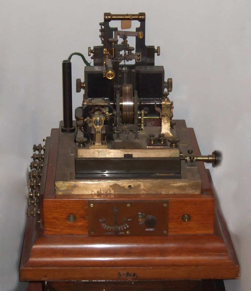
By the end of the 19th century a number of sensitive relays had been developed, and in 1899 Sidney George Brown patented his drum relay, which was used in many cable stations until the advent of electronic signal amplification. The working of the Brown Drum Relay is described below. The description is from a 1928 technical manual.
Brown Drum Relay Patents:
GB Patent 1434 of 1899
US Patent 648,919 issued 8 May 1900 |
| --Bill Burns |

Brown Drum Relay
Base size 16" x 19", weight 100lbs+ |
Brown Drum Relay. Many efforts have been made to automatically repeat cable signals from one cable to another by means of a relay in order to reduce operating expenses at repeating stations and to provide rapid direct communication between the terminal stations. The two main difficulties with the successful operation of a cable relay are: first, that of securing a proper electrical contact; and second, the lack of uniformity or definition of the signals, which results, among other things, in what might be termed a wandering zero, or the failure of the pointer to return to the same position for all zero intevals of current.

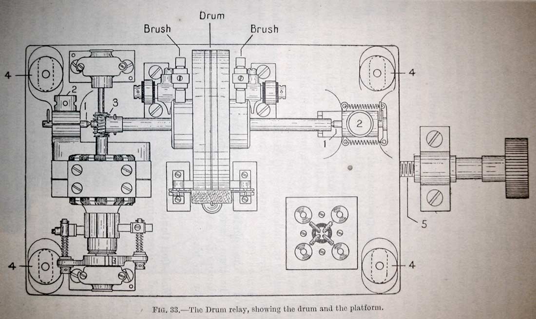
Fig 33. The Drum relay, showing the drum and the platform. |

The drum |
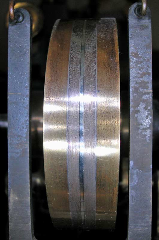
Action of Relay. These obstacles were first overcome with considerable success by the invention of the drum cable relay and the magnetic shunt by Mr. S.G. Brown. This relay is an instrument of the D’Arsonval galvanometer type and is actuated in the same manner as a siphon recorder. The coils control the the movement of a front suspension which carries a tongue consisting of a light glass tube, through which passes a fine platinum wire tipped with iridium which presses lightly on the surface of a rotating drum. This drum, which is rotated by a motor at a speed of about 150 revolutions per minute, is built up of three silver rings. The center ring is insulated from the others by thin mica discs and constitutes a neutral portion, or "no man's land," on which the tongue rests when no signals are passing. It was found that good electrical contact could be maintained with a light pressure between the iridium point and the moving silver surface of the drum if the contact were shunted by a 2-microfarad condenser and that the frictional resistance of the tongue to the side motion could be made very small by moving the surface on which it rested parallel to the direction of the tongue.
Regulating Friction between Drum and Contact Point. The friction that is present is useful in damping the motion of the coil, but in order to secure uniform signals it must remain constant. As an aid to this the surface of the drum must be quite smooth and free from pits with a dull mat appearance, but it cannot he highly polished as the electrical contact is not good between the iridium point and such a surface. The pressure of the pointer on the drum and its speed of rotation are other important factors affecting the frictional resistance to the lateral motion of the pointer.

Magnified view of drum surface showing
the
three silver contact strips separated
by
mica
insulators.
The drum is ¾" across. |
Coil Suspension. The coil is suspended by a single, fine, phosphor-bronze ribbon top and bottom, and is connected to the pointer suspension by two fine quartz fibers. It has two windings; the main windinghas a resistance of 500 ohms and is connected to the cable in the usual manner; and the auxiliary winding, or correcting coil, has a resistance of 120 ohms and is connected to the local circuit as shown.
Bibliography: The Eastern Associated Telegraph Companies Text Book on Cable Engineering. Volume III Part Fifth: Reception of Signals by G.N. Perkins. London 1928.
|