Introduction: This article on cable transmitters was published in the All America Review for April, June, and September, 1921. The Review was the house magazine of All America Cables, Inc.
Nelson J. Perryman joined All America in 1915 after working for a number of years for the long-established English cable consulting firm of Clark, Forde & Taylor. He eventually rose to the position of Assistant Vice President before retiring in 1950. See “Around the World: A Career in Cables” for a short biography of Nelson Perryman by his grandson, Jon Clark. |
| –Bill Burns |
Cable Transmitters
By N. J. PERRYMAN,
Superintendent of Apparatus and Equipment
All America Cables, Inc.
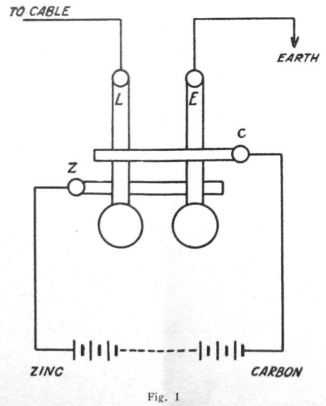
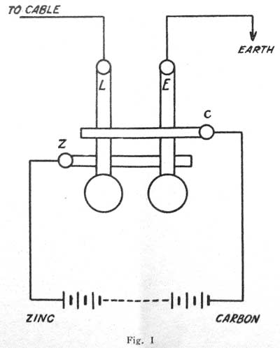
THE simplest method of sending signals into a submarine cable is by using a hand key provided with double contacts levers and wired up as shown in Figure 1. The two levers L and E are joined to the cable and earth respectively. Normally these levers are pressed up, by springs, against the bar C and electrical connection is made between the bar C and Levers L and E by means of platinum contacts.
Either lever can be depressed until it is in contact with the bar Z, platinum contacts being used as in the case of bar C.
The signalling battery is connected between the bars Z and C, the negative pole being joined to Z while the positive pole is joined to C.
Under these circumstances when lever L is depressed until contact is made with bar Z the negative pole of the battery is applied to the cable while the positive pole is put to earth through the contact between C and E.
On our system this constitutes a dot signal.
The dash signal is formed when lever E is depressed, this puts the positive pole of the battery to the cable and the negative pole to earth.
 |
This hand key is still in use on a few slow speed circuits. When high speeds are necessary or when absolute uniformity of sending is required a mechanically operated key must be used.
To make a success of a relay chain or render automatic reperforation of slip possible it is vitally important to secure absolute uniformity of sending.
For this reason all our main stations have been equipped with automatic transmitters. To get the best out of an auto it is very necessary that its purpose and construction be fully understood.
The purpose of the auto is really
to operate the levers L and E (Fig. 1)
mechanically. Now the form of
key shown in Fig. 1 does not lend itself readily to mechanical operation, hence the first thing that has to be done is to remodel this key.
This remodelled key is called the local transmitter and is illustrated in Fig. 2. The lettering of Figs. 1 and 2 is exactly the same so that the description of the operation of the key shown in Fig. 1 applies also to the key shown in Fig. 2.
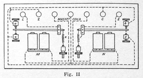 |
In Fig. 2 the left hand lever is the dot lever, the right is the dash lever.
Under the influence of the springs (e) and (f) both levers normally rest on the contacts (a) and (b). As indicated by the dotted lines, contacts (a) and (b) are joined by internal wiring to the terminal C and thence externally to the positive pole of the signalling battery.
In the same way contacts (x) and (y) are wired internally to terminal Z and then externally to the negative pole of the signalling battery.
In Fig. 1 the levers are manipulated by the fingers of the operator; in Fig. 2 small electromagnets M and N control the movement of the levers.
The dotted lines show the internal wiring and it will be seen that the centre terminal is joined to both magnet windings while the other end of each winding is joined to separate terminals situated one on each side of the centre terminal.
When a current of sufficient strength is made to pass through its magnet coils, the magnet M is energized and so attracts the iron lever L until contact between the lever and stop (x) is made. This contact continues and a dot current is sent to line so long as the energizing current is applied.
Similarly a dash current is sent to line when the magnet N is energized.
In Fig. 2 it will be seen that terminals L and E are joined internally to the brass supports for the pivots on the levers. To ensure good electrical connection with the lever a small flexible spiral of copper wire is connected between the lever and the brass support.
Generally speaking the magnets M and N are wound so that the total resistance of each set of magnet coils is approximately 50 ohms.
A four (4) volt storage battery is used to operate the magnets M and N which means that the energizing current in the magnet coils is 80 milliamperes.
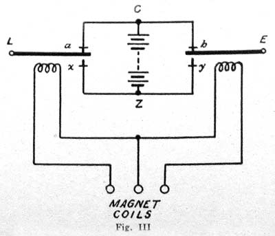 |
For convenience the local transmitter is shown in Figure 3 in a purely diagramatic form. The lettering remains the same and the signalling battery is shown connected up.
The method of operating the local transmitters has now to be considered. The instrument used for the purpose is the Automatic Transmitter, more generally known as. the "Auto."
Most of our operators are quite familiar with the external appearance of the auto, but regard its internal mechanism as something of a puzzle.
Our purpose will therefore be to consider the auto in sections and build up in this way a conception of the whole.
 |
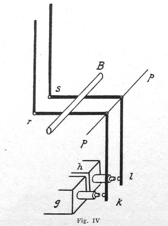
Figure 4 illustrates the two contact levers (rk) and (sl) which appear at the front of the auto under the glass cover. The sketch is intended to be a perspective one with the lever (rk) in front or nearer to the reader and (sl) behind. Under these circumstances (sl) is the dot controlling lever and (rk) the dash controlling lever.
Both (rk) and (sl) are rigid levers of rightangular formation and each moves as a whole about a pivot (pp). A spring, not shown in the figure, keeps each lever pressed up against a bar B. This bar has an up and down motion imparted to it by virtue of which contacts (k) and (1) are caused to make and break contact at (g) and (h) respectively.
Contacts (g) and (h) are mounted on a hard rubber base and hence are insulated from each other and from the framework. (g) and (h) are provided with terminals for wiring to external circuits.
The pivot (p) which is electrically connected to both levers (rk) and (sl) is also provided with a terminal and serves to connect up with one pole of the four volt battery required to work the local transmitters.
Figure 5 shows diagramatically the method of wiring up the auto parts, illustrated in Fig. 4, to the local transmitter, illustrated in Figs. 2 and 3.
Internal wiring in each piece of apparatus is indicated by dotted lines, the full lines show the external wires joining the terminals of the pieces of apparatus.
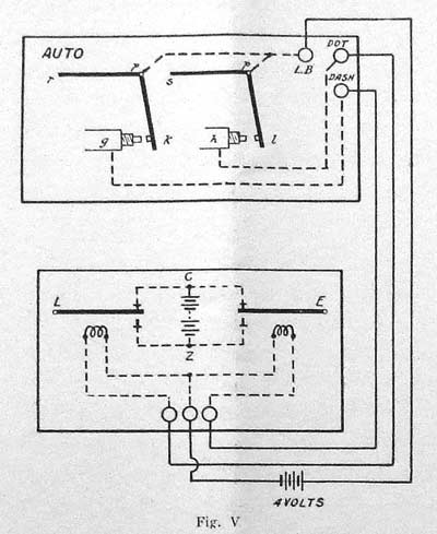 |
To avoid misunderstanding attention is here called to the fact that the Auto is provided, at the side, with a switch labelled "Key"---"Auto." This switch is ignored in the diagram but it is assumed that the switch has been moved over to the side marked "Auto" when the dotted lines shown in Fig. 5 represent the internal connections.
The local battery of four (4) volts is seen to be joined between the junction of the local transmitter magnet coils and the common point (p) of the two auto levers. The insulated contacts (g) and (h) are joined respectively to the dash and dot magnet coils.
If now the lever (sl) is allowed to come in contact with contact (h), the local battery will send a current through connection (p) and contacts (lh) to the dot magnet coil and through the latter back to the local battery. The energizing current being thus established the lever L is attracted and a dot signal sent from the signalling battery CZ to the cable.
Similarly if the lever (rk) is allowed to come in contact with contact (g), the local battery will energize the dash magnet coil and by attracting lever E a dash current will be sent from the signalling battery CZ to the cable.
If now both levers (rk) and (sl) are allowed to make simultaneous contact with stops (g) and (h) then two currents will flow, one through the dot magnet coils and the other through the dash magnet coils. Both levers L and E are therefore simultaneously attracted and both make contact with the Z terminal of the signalling battery so that no current goes to cable from the latter.
We now have to consider how the movements of the levers (rk) and (sl) are controlled in order to send dots or dashes to the cable at will.
The driving force of the Transmitter Automatic is supplied by a motor of the "mousemill" type. This motor is contained in the base of the auto, the rotating element is a heavy brass cylinder, the axis of which is mounted on ball bearings.
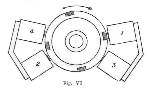
On the circumference of this cylinder and parallel to its axis are embedded four soft iron bars spaced at equal distances apart as illustrated in Fig. 6.
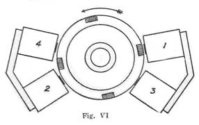 |
Four pairs of coils are arranged as shown in the figure and the pairs of coils have been marked 1, 2, 3 and 4. In the position illustrated the armature has been drawn with one of its iron bars opposite the coils marked r. In this position the commutator (Fig. 7) is so adjusted that the current has just been cut off from coils r and is about to be applied to the coils marked 2.
Coils 2 thus energized will attract the iron bar nearest to them and so give an impulse to the armature causing it to rotate in the direction of the arrow.
At the moment the bar is opposite coils 2 the commutator cuts off the current and applies it to coils 3. This operation is continuously repeated, the coils 1, 2, 3 and 4 being energized in their numerical order and a continuous rotary motion is imparted to the armature. The armature is made heavy to give a fly wheel effect and prevent the motion being jerky.
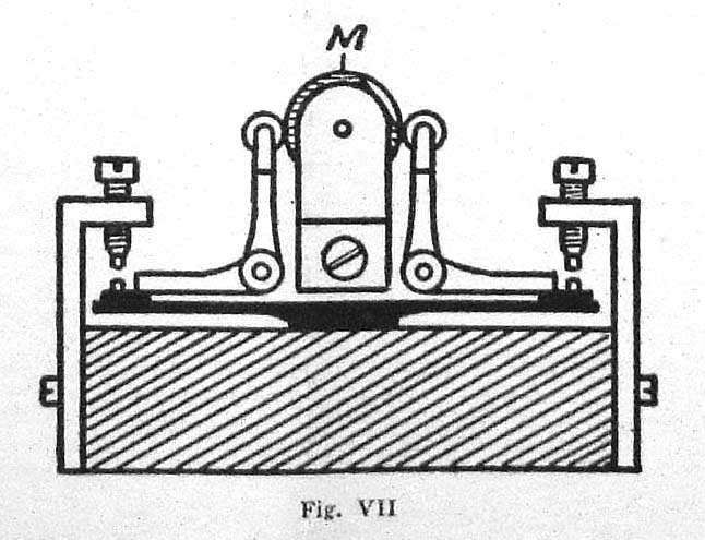
There are four contact makers on the commutator, two of these are illustrated in Fig. 7 and the other two are directly behind those shown.
A cam M rotates between the two contacts illustrated and a second cam on the same spindle actuates the other two contacts.
Each cam consists of a circular disc with a flat filed on the edge. The second cam is fixed on the shaft so that the flat on its edge is at right angles to the flat on the first cam.
The cams M are so arranged that the current passing through the four contacts which they actuate is never on more than one pair of coils at a time.
The axle of the cams is arranged by means of gear wheels to revolve four times for one revolution of the armature, hence each pair of coils is energized once while an iron bar (Fig.. 6) moves forward a quarter revolution.
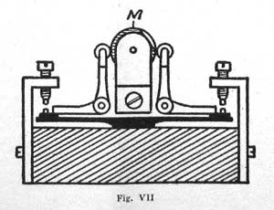 |
The contact levers (Fig. 7) are bent at right angles to avoid oil getting on the contacts and when oiling the bearings of the motor care should be taken not to allow the oil to spread over these contacts.
To avoid sparking at these contacts small condensers are joined across each. These condensers are mounted in the base of the auto.
When the motor commutator is in correct adjustment no sparking is visible at the platinum contact points. Daily attention is required to see that these contacts are kept clean, a small fine file is generally used to ensure good metallic contact. Any variation in contact is reflected in speed fluctuations with consequent trouble at relay and auto puncher stations which are served by the auto in question. For this reason it is necessary to emphasize that constant careful attention
must be paid to the motor commutator contacts.
The same remark applies to the contact on the governor arm situated under the circular glass cover on the front of the base of the auto.
The governor is of the centrifugal type. Two fairly heavy weights are pivoted to the front end of the armature (Fig. 6) and arranged so that when they move outward, as a result of the increase of speed, they press against the end of the movable rod R (Fig. 8).
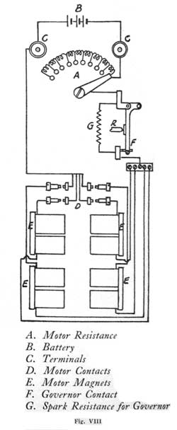 |
This rod R is free to move laterally so that the motion is transmitted to the front lever F and causes it to break contact and so reduce the speed. To prevent a complete break in the battery circuit, the contact on lever F is shunted with a resistance G. To a great extent this eliminates sparking at the governor contact but care should be taken to see that the contacts are kept clean.
Particular attention should also be given to the axle on which the lever F works. If the movement is allowed to become stiff then fluctuations will take place in the speed.
The contact on rod F is kept closed under normal conditions by means of a spiral spring. The tension of this spring is balanced by the thrust of the rod R until the speed becomes excessive when the thrust of R overcomes the tension of the spring.
The tension of the spring is adjusted by means of the micrometer screw attached to the governor mechanism and by means of this screw the speed of the auto is set.
The motor battery should provide sufficient power to drive the transmitter and still have a little surplus. Without this small reserve the governor cannot be depended upon. To ascertain whether there is any reserve power the contact lever F should be pressed with the finger for a few seconds.
The pressure prevents the contact being broken and allows the full power of the battery to operate. If there is sufficient surplus of battery power the contacts will visibly separate for a few seconds after the pressure is removed. If this result does not appear, the current is insufficient and should be increased, as without a good reserve of power the governor is useless.
This test, of course, should not be made while traffic is passing through the auto.
Having described the means by which the rotary motion is obtained, we have now to see how this motion is made use of in operating the transmitter mechanism of the auto.
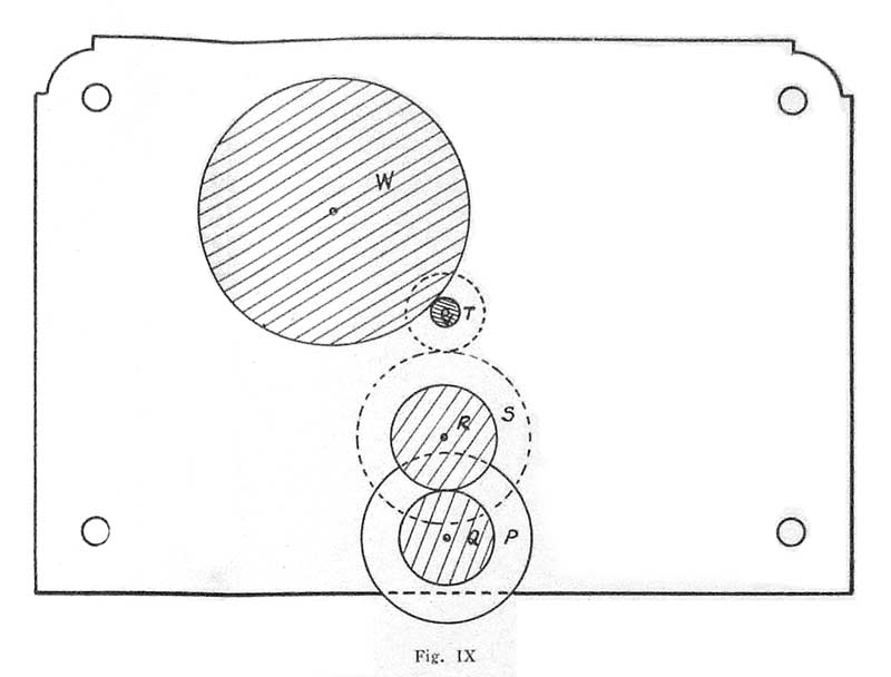
Fig. 9 shows the cogwheel train which would be visible if the front plate of the auto were removed.
 |
The driving pinion is mounted on the motor commutator shaft and as mentioned above this shaft rotates four times for each revolution of the motor armature. This driving pinion gears directly in toothed wheel P. Mounted in front of P and fixed to the same shaft is the toothed wheel Q, shown shaded. Wheel Q gears into toothed wheel R. The shaft on which R is fixed passes out through the back plate of the auto. At the back of the auto, and on the outside, the toothed wheel S is mounted on the same shaft as R. Also at the back of the auto, and on the outside, the toothed wheel F engages in S.
On the same shaft as T but inside the auto the small wheel V is fixed and this wheel engages in the teeth of large wheel W.
The object of placing wheels S and T on the outside of the auto is to permit of alterations in the speed range.
The governor is designed to work well over a certain range of speeds. If this range is required to be changed we remove wheels S and T and substitute another pair which will give the range desired.
In deciding what pair of gear wheels to use the idea to be borne in mind is that the governor operates best when the motor armature is kept rotating at its highest speed.
The shafts on which W and V are mounted are arranged to project through the front plate of the auto and there carry the spur wheel X and small wheel Y respectively, see Fig. 10.
The wheel W has ten times as many teeth as the wheel V hence for one revolution of V we only get one tenth of a revolution of W. Now on the spur wheel X we have ten teeth, each tooth being of a circular section of a size to fit the center line of holes in the perforated tape.
It is therefore seen that for one revolution of the wheel Y the spur wheel X will advance one tooth. On the wheel Y a small pin is mounted on which is pivoted the lever cb. ab is another lever pivoted at both a and b. B is a rod (see fig. 4) which is rigidly fixed to lever ab and hence moves with it.
By the rotation of Y and the action of levers, ab and bc, about the fixed point a, it is easy to see that the rod B receives an up and down motion, thus striking and carrying down lever spl which is pivoted about p. in this way the contact hl is broken.
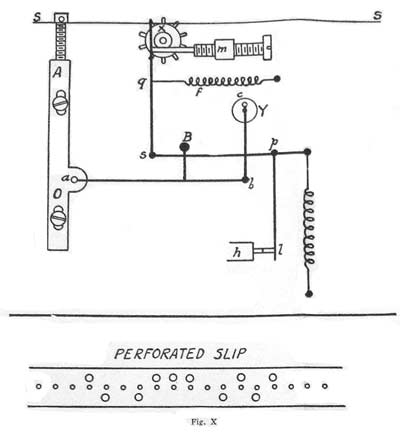 |
When the perforated tape passes along the platform SS by virtue of the rotation of X the lever sp is made, as we have seen, to move up and down and this motion is passed on to the pecker rod sq. When this rod presses against a plain part of the perforated tape the contact hl is held open. If a hole in the tape is presented to the pecker rod the latter passes through the hole and so establishes contact at hl.
The rod qs is in this case carried forward by the movement of the tape, but as soon as rod B comes down and presses against sp it pushes the rod clear of the hole and the spring f brings the rod back against the stop m ready for the next signal.
Only one set of levers is shown in fig. 10. Actually there are two sets working, one each side of the wheel X. The lever B acts on both sets of levers.
In this way dots or dashes are sent from the transmitter according as the pecker rods pass up through holes on the top or on the lower part of the tape.
Care has to be taken in adjusting the screw m. The auto mechanism is turned until the pecker rods are just about to appear above the plate SS. In this position screws m are adjusted so that the pecker rods are in a straight line with the tooth showing on wheel X.
Rod B can be caused to break contact at hl early or late by lowering or raising the bracket AO to which the pivot a is fixed. This adjustment therefore changes the percentage duration of contact at hl.
In previous articles we have dealt with the old type of Muirhead auto with which many of our stations have been equipped.
Improvements have been effected in various details until quite recently a greatly modified model has been brought out. A number of our main stations have been equipped with this new model, hence a few notes on the subject will be of value.
The motor unit in the new
style auto is a small standard electric motor designed to run on a direct current 8-volt supply.
The windings on the rotating armature are brought out to a commutator which connects with two brush contacts. These brushes are brought out to terminals marked A on the top of the motor. The fixed windings forming the field coils of the motor are brought to terminals marked F. It will be seen that there are only three terminals on the top of the motor so that one of them is common to both field and armature windings. The remaining two terminals permit of a resistance being joined in series with the field coils in case it is found necessary to vary the speed of the motor itself.
The motor is mounted in a slide on the main base and this permits a damaged motor to be readily exchanged for a good one.
To avoid difficulties in securing exact alignment the motor is connected with the rest of the auto through a flexible coupling. The other side of this coupling is fixed to a main shaft carried on a double bracket. Between the two bearings of this bracket there is a governor which consists of two sleeves. One sleeve is fixed to the shaft while the other sleeve is free to slide on the shaft. The two sleeves are joined by two springs in the form of thin flat steel strips and to the center of each strip a weight is fixed. A spiral spring slipped over the main shaft serves to keep the loose sleeve at its maximum distance from the fixed sleeve until the speed of rotation causes the two weights to fly out thus bending the steel strips and compressing the spiral spring to allow the loose sleeve to slide back towards the fixed sleeve.
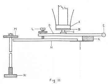 |
On the forward face of the loose sleeve A (Fig. 11) there is a steel disc B. In rubbing contact with B is a stud C which is carried on a lever D. This lever is pivoted at E and a spiral spring attached to it keeps the stud C always pressing up against the steel face B. A second lever H is attached to the first lever D by means of a flat spring I and the two levers are electrically insulated by means of insulating strips at K.
An adjustable contact screw L passes through lever D and makes contact with lever H. The current supply to the electric motor passes through the contact L and in this way the contact L controls the operation of the motor.
M is a fibre disc which acts as a stop for lever H. The position of this disc is controlled by screw N on the front auto plate.
As the motor speeds up the loose sleeve A moves back due to centrifugal force acting on the governor weights. Lever D which is pressing C on the face of B also moves back and carries lever H with it until the latter touches the stop M. Lever H being now fixed any further backward movement of D will cause the contact at L to open thus reducing the current supply to the motor, which will slow down. In this way the motor will maintain a definite speed determined by the position of stop M.
The best working of the auto is obtained when the motor speed is adjusted by means of external resistance to be a trifle higher than the circuit speed required. The gentle operation of the governor will then keep the speed at the desired circuit value.
At the end of the main shaft, which carries the governor, is the driving pinion. This pinion gears in another wheel on the secondary driving shaft. These two wheels have an identifying letter stamped on them, the larger wheel is stamped B while the smaller wheel is stamped A.
When A is driving we get the lower series of speeds while B as a driver gives the higher series. For this purpose A and B are interchangeable on their two shafts; these are the only gear wheels supplied.
On the front of the auto is a speed dial, the rim of which is removable. On one side of this rim is a speed scale labelled A for use when wheel A is the driving wheel on the main shaft. On the reverse side is the speed scale B for use when wheel B is on the main shaft.
For the speeds generally in use on our circuits scale A should be used and wheel A should be on the main shaft.
The front part of the auto acts more or less in the way described in the previous article (see fig. 10).
The main point of difference is in the arrangement of clearing the peckers out of the holes in the slip at the end of a signal. In the previous case discussed (fig. 10), the clearing was done by means of levers abc and rod B. In the new auto the rod B is, of course, retained but the operating mechanism is different.
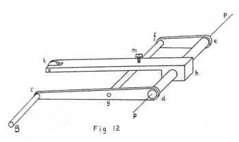 |
Fig. 12 shows diagrammatically the new arrangement. B is the rod which bears on the pecker lever. Rod B is fixed to an arm cd which is part of a framework cdefg. This framework pivots on
a shaft indicated at pp. Lever hk
also pivots on shaft pp and a
screw m passes through lever kh
and bears on rod fg. At the end
k is a hard roller which bears upward on a cam (not shown).
When the cam rotates it depresses roller K and hence lever
kh. This in turn causes screw m
to bear down on rod fg thus turning the framework cdefg about
pivots pp. Rod B is thus forced
down on top of the pecker levers
and produces similar results to
that discussed in connection with
fig. 10. A spring fixed to lever
cgd keeps the roller k bearing
up against the cam.
By means of a screw on the front of the auto, the lever can be made to travel backwards and forwards on the shaft between e and d. Roller k is thus made to bear on different parts of the cam surface and so the "efficiency" of the auto is adjusted to the required figure.
It will be noted that the base of the new auto consists of two parts. The lower part is a
wooden framework which should be screwed down to the operating table. On the framework there is a tablet carrying seven springs with connection screws for wires. The permanent auto wires should be fastened to this tablet so that the top of the auto can be lowered into place and held secure by means of the two screws (one at each side) on the sides of the auto.
Under this system the connections are made by the spring clips in the base and these clips should be verified to see they have sufficient "spring" to give a good contact. To change an auto no wires are touched, the auto top is lifted off the framework and a new top substituted.
This article completes the discussion of cable transmitters; if
any points are in doubt I shall welcome queries sent to this office by any of our men who are interested so that the technical columns of our "Review" can be made to fill a real need.
|