Introduction:
The near success of the 1865 Great Eastern Atlantic cable expedition revealed some shortcomings in the paying out and picking up machinery, which were remedied by mechanical engineer Henry Clifford for the 1866 expedition. Clifford was then Chief Engineer of the Telegraph Construction & Maintenance Company (Telcon), which had complete responsibility for the manufacture and laying of the 1866 cable. The author of this article, George Elliot, was one of the principals of Telcon.
The article as published in the Proceedings of the Institution of Mechanical Engineers in 1867 was illustrated only by line drawings. I'm grateful to the Institution of Engineering and Technology Archives for permission to also reproduce here their photographs of the cable machinery on Great Eastern in 1866, a set of eleven images titled “Atlantic Telegraph Machinery on board the SS Great Eastern.” |
| —Bill Burns |
INSTITUTION
OF
MECHANICAL ENGINEERS.
PROCEEDINGS.
1867.
PUBLISHED BY THE INSTITUTION,
81 NEWHALL STREET, BIRMINGHAM.
DESCRIPTION OF THE
PAYING-OUT AND PICKING-UP MACHINERY
EMPLOYED IN LAYING THE
ATLANTIC TELEGRAPH CABLE.
By Mr. GEORGE ELLIOT, of London.
The Atlantic Telegraph Cable expedition of 1866 was twofold in its purpose, the first object being to lay a new cable, and the second to recover and complete the one commenced and lost in the unsuccessful attempt of the previous year. The general arrangements on board the Great Eastern steamship, which was employed for the purpose on both occasions, were similar in both years; but the knowledge and experience which had been so dearly bought in 1865 rendered necessary many improvements and alterations in the detail of the apparatus employed.
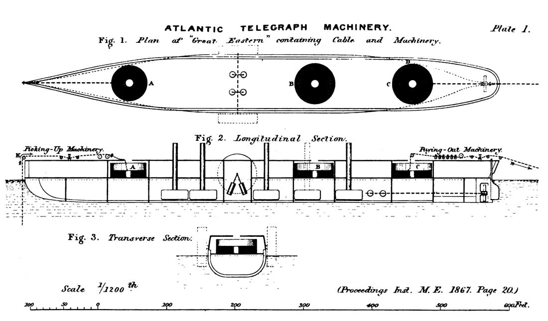
The cable itself was coiled in three circular wrought-iron tanks, which were built on the main deck of the ship, as shown in Figs. 1, 2, and 3, Plate 1, which represent a general plan and longitudinal and transverse sections of the vessel. The foremost tank A occupied the space which had previously been the forecargo space; and the after tank C was placed in what had been the aftercargo space. The middle tank B occupied what had been the second dining saloon; and the funnel (shown by the dotted lines in Fig. 2) from the pair of boilers in that position was removed for the purpose, those boilers being thrown out of work during the expedition. The whole of the fittings in these spaces had been removed, and each of the tanks was stayed to the sides of the ship by two flat frames of iron, built on angle-iron framing, thus securing the tanks in the most substantial manner. The deck had also been shored underneath by baulk timbers, which were carried through from deck to deck down to the bottom of the ship.
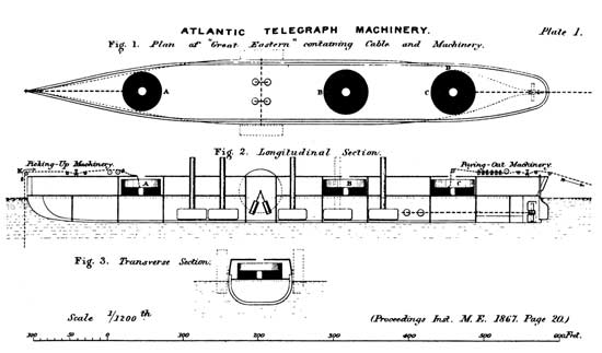
Plate 1 |
The fore tank was 51 ft. 6 ins. diameter, the middle tank 58 ft. 6 ins., and the after tank 58 ft. 0 ins.; they were all of a uniform depth of 20 ft. 6 ins., and similarly constructed in all respects. The bottoms were ½ inch thick, lap-jointed; and the sides were ⅝ inch thick in the lower half; and ½
inch in the upper half. The sides were butt-jointed, so as to present a perfectly smooth surface inside; and the bottoms were covered with a thin wood floor to receive the cable. As it was of vital importance that the cable should be kept always under water, to prevent depreciation of the gutta-percha coating, and also to afford the only means of effectually testing its electrical condition, these tanks were carefully made water-tight. In paying out the cable, the water in the tanks was kept somewhat below the level of the top flake, and required to be lowered during the paying out; for this purpose each tank was supplied with discharge valves, and as the bottoms of the coils were above the water line of the ship, as shown in Fig. 2, it was only necessary to open these valves in order to allow the tanks to discharge themselves completely.
The coiling of the cable into the tanks, out of the hulks by which it was brought from the Telegraph Construction and Maintenance Works at Greenwich to the Great Eastern at Sheerness, was effected in the following manner. The cable was brought up over the side of the ship from the hulk, upon wheels which guided it on to a large deep-grooved wheel driven by steam power; on the tread of this wheel ran a small jockey wheel or roller, pressing the cable down into the groove of the large wheel, so as to give sufficient friction for enabling the wheel to draw up the cable from the hulk. The coiling commenced from the outside of the tank, the end being previously triced up above the tank, leaving a clear end for splicing and testing. The first turn of the cable was carefully laid round the outside of the tank, and the next was laid back close up against the previous turn, and so on until a perfectly flat flake or layer was laid into the eye of the coil, which was left about 9 ft. 6 ins, diameter. The cable was then led out direct to the outside of the tank, across the coils already laid; and another flake was commenced precisely similar to the first, this process being continued until the tank was filled. The direction of lay-out of the cable from the end of one flake to the beginning of the next was tangential to the circle of the eye of the coil, as shown at D in the plan, Fig. 1; and the portion of cable crossing the coils was protected from the weight of the coils above by wood battens laid on each side of it, about 3 inches wide and 1 inch thick with the edges rounded. When the coiling down of the cable into the tanks was finished, eyes were fitted into the centre of each coil, which were telescopic in their construction, so that as the cable was paid out the eyes could be lowered from time to time. Men were stationed in the tanks for the purpose of keeping the cable always clear during the paying out.

Plate 2 |
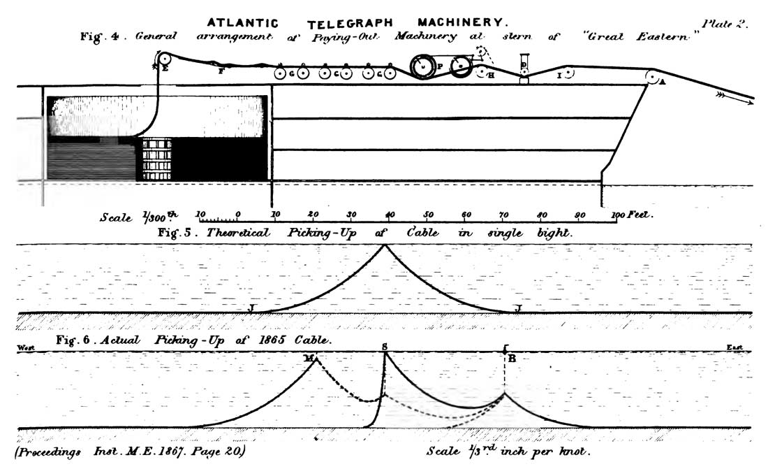
In paying out the cable it was passed up to the hatch over the centre of the coil, and carried over a large wheel E about 4 feet diameter, as shown in the enlarged longitudinal section, Fig. 4, Plate 2. The cable was then carried in a trough F about 2 feet wide, made of sheet iron, leading to the paying-out machinery; this trough was fitted with rollers at about 10 or 12 feet intervals to relieve the cable from friction in passing along, until it reached the paying-out machinery, which was placed in the stern of the ship, slightly to the port side.
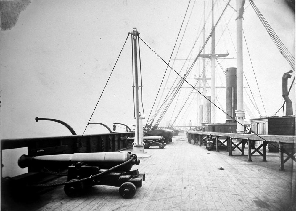
2. View of Upper Deck of Great Eastern showing Troughs for conveying Cable from Tanks
Image courtesy of IET Archives |
The length of cable in the after tank was 840 knots (1 knot = 6084 feet = 1.15 statute mile), in the middle tank 865 knots, and in the fore tank 671 knots; and the entire length of 2376 knots was joined up into one continuous length of cable before the laying was commenced. The size of the cable was 1⅛ inch diameter, and its weight 31 cwts. per knot in air, and 14¾ cwts. per knot when immersed in water; the breaking strain was 8.10 tons, equal to eleven times its weight in water per knot, so that the cable would just bear its own weight in 11 knots depth of water.
3. Showing the Cable as it enters and passes through the Machinery, after leaving the Trough which conveys it from the Tank
Image courtesy of IET Archives |
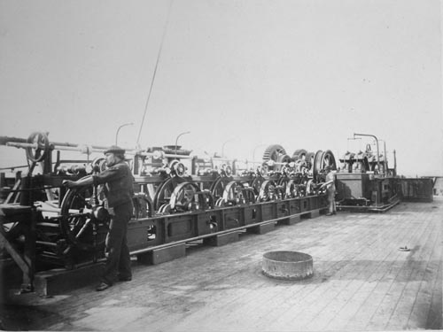
Paying-Out Machinery.—In the paying-out machinery the chief object to be attained was to supply some means of checking the cable in the most regular manner possible while passing out of the ship, and also of keeping it in a state of constant tension; and it was required that the amount of this tension should be at all times known, and that it should be regulated by the depth of the water in each particular part of the ocean, and also to some extent by the speed of the ship.
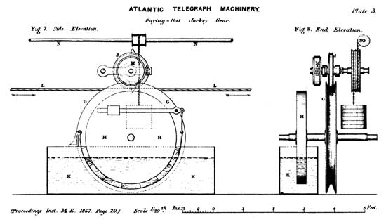
Plate 3 |
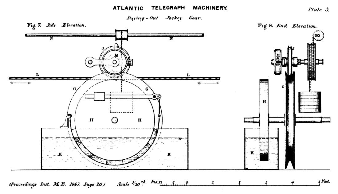
The most important feature is the arrangement by which it was rendered impossible that more than a certain strain should be kept upon the cable during the paying out. A less strain would only involve a slight loss of cable; but any increased strain might possibly damage or even destroy it. The cable on entering the paying-out machinery was passed over a series of six deep-grooved wheels, each about 3 feet diameter, one of which is shown in side and end elevation at G in Figs. 7 and 8, Plate 3. On the shaft of each wheel G was fixed a friction wheel H of the same diameter, to which was fitted a friction strap lined with wood and tightened by a weight on a lever, as shown in Pig. 7; to prevent any unnecessary wear, this friction wheel ran in a tank of water K. Above each of the grooved carrying wheels was a jockey wheel J about 14 inches diameter, pressing the cable L down into the groove of the carrying wheel G, and hooped with an india-robber tyre to form a soft cushion, so that no damage might be done to the cable. The jockey wheel was also fitted with a small friction wheel M having a wrought-iron strap adjustable by a screw. Any one of the jockey wheels could be lifted up, so as to allow the cable to slip freely through the groove in the carrying wheel; or in case of necessity the whole set of jockey wheels could be raised at once by a man stationed at a large hand wheel, like an ordinary ship's steering wheel, turning the longitudinal shaft N which lifted up each jockey wheel by a chain winding upon the shaft. In practice there were generally about four of these wheels kept at work, but the machine was made with six in case of need.
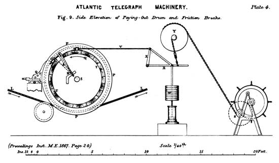
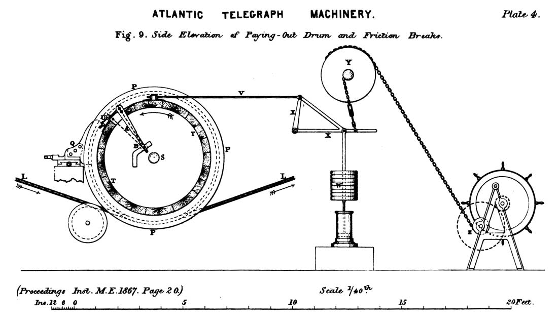
Plate 4 |
After the cable had passed through this part of the machinery, called for distinction the Jockey Gear, and had thereby been subjected to a slight amount of strain, it was led to the main Paying-Out Drum P, shown in side elevation in Fig. 9, Plate 4, and in end elevation in Fig. 10, Plate 5. The cable L entered on the underside of the drum, Fig. 9, and was passed four times round, as a rope is passed round a capstan, and for the same purpose of getting a firm hold upon it. Just above the point at which the cable was led on, a knife-guide Q was placed for fleeting or slipping sideways the coils already on the drum, so as to leave a clear lead-on for the fresh cable; this guide was adjustable in both directions with screws, like a slide-rest on a lathe. The shaft S of the drum was carried through on each side, one end being fitted with a coupling R, which will be referred to afterwards in connection with the picking-up arrangements adapted to this machine; and on the other end were fitted the main friction breaks T T.
These Self-Adjusting Friction Breaks were invented by the late Mr. Appold, and it is interesting to note that they were the identical breaks used in the first attempt to lay the Atlantic cable in 1857. The break wheels themselves T T, Figs. 9 and 10, of which there were two on the shaft, were 4 ft. 6 ins, diameter, and 12 inches wide on the tread, which was turned a little convex. On each wheel was fitted a wrought-iron strap lined with wood, and a screw adjustment U admitted of any required amount of friction being obtained. On the top of each break strap was a lug, to which a long rod V was fastened, leading to the top of a bell-crank lever X with arms in the proportion of 11 to 1; and to the long arm of this lever was suspended a rod carrying a number of weights W, which were removable at pleasure for adjusting the strain. The rod was continued below the weights, and had a piston attached to it working loosely in a water cylinder, to prevent any sudden jerking action from coming on the break. By screwing up the adjustment U, the break was made to have sufficient friction for lifting the weights on the suspension rod.
4. A Sectional View of No. 3, showing the large Brake-wheels and the Cable as it passes four times round the Drum-wheel.
Image courtesy of IET Archives |
In order to render the break self-adjusting, so that it should relieve itself whenever binding too hard, the break strap was cut through, and the ends were attached to a lever A in the manner shown in Fig. 9, the lower extremity of the lever being free to move in a slot cut in the stationary bracket B. When the break was binding too hard, so that it began to lift the weight W too high, the break strap consequently travelled round and brought the lever A into the position shown dotted. The attachment of the one end of the break strap at the extremity of the lever moved then through an arc of a larger radius than the attachment of the other end of the strap; and the result was therefore equivalent to lengthening the break strap and slackening the break off the surface of the wheel, causing the weight W to fall back instantly to its original position. The consequence of this action was that when the break was at work the lever A kept the strap just tight, and the weight W continued just oscillating. The two break wheels T T, placed side by side on the drum shaft, Fig. 10, were both fitted precisely alike throughout.
Near the end of the bell-crank lever X, Fig. 9, a chain was attached leading to a wheel Y overhead; and from a larger wheel on the same shaft another chain led to a barrel on a winch Z. A man standing at this winch by turning the hand-wheel could immediately take all the weight off the breaks T T. The whole of this paying-out machine was made double, so that in case of any mishap there might be no delay, but the cable might at once be removed from one drum to the other. This provision however fortunately proved to be needless, as throughout the expedition there was no failure in any part of the machinery, its action having been in every particular perfect.
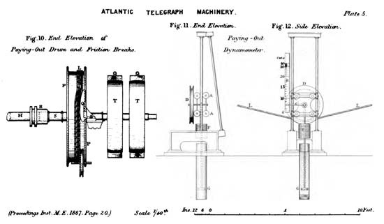
Plate 5 |
The cable having by these means been sufficiently checked was passed over the stern wheel A, Fig. 4, into the sea; and on its way the actual strain was measured by a Dynamometer placed at D, consisting of the following arrangement. Immediately on the cable leaving the paying-out drum P it passed over a wheel H, and at a distance of 23 ft. 6 ins. over another similar wheel I; and in the centre between these two wheels the dynamometer D was fixed, which is shown in Figs. 11 and 12, Plate 5. It consisted of a wheel D weighted to a particular amount and riding upon the cable L, being guided in a fixed vertical frame by rollers A A. The amount of deflection evidently varies according to the strain on the cable, and the strain was calculated from the formula obtained by the ordinary resolution of forces, namely S = l/4d W approximately; where S = strain, and W = weight of dynamometer wheel D, both in the same terms; l = distance between centres of carrying wheels H and I, Fig. 4, and d = deflection of cable. The values of d or amounts of deflection were calculated for all strains from 7 cwts. up to 40 cwts., and a scale B was affixed to the instrument with an index C carried upon the wheel D; so that the strain could immediately be read off at all times by simple inspection. The total weight of the wheel D and its suspended weight F was 426 lbs.; and the rod carrying the weight F was continued down to a piston G working freely in a cylinder of water, to prevent any sudden jerks of the dynamometer. The ordinary strain in paying out was found to vary from 10 to 12 or 14 cwts., and at no time exceeded 16 cwts.

5. Showing the Dynamometer used for indicating the amount of strain on the Cable, and the Cable as it passes over the stern.
Image courtesy of IET Archives |
The paying-out drum was also supplied with steam power for reversing its action and picking up the cable, should any fault occur requiring such an operation. This constituted one of the most important improvements over the arrangements of the 1865 expedition, in which it had been necessary to hand the cable along the side of the ship from the paying-out machinery in the stern to the picking-up machinery in the bow, on any occasion of requiring to haul in the cable; and it was during this hazardous process that the cable was broken and lost in the former expedition. In the present machinery the shaft S of the paying-out drum P, Fig. 10, was prolonged on one side for the purpose of forming a coupling to the picking-up arrangement. It was considered advisable to make all this part of the machinery sufficiently strong to work with, and if necessary even to break, the large grapnel rope, which had a breaking strain of more than 30 tons. The shaft S was therefore made in its smallest place 7½ inches diameter. There were three points to be specially considered in the design: first, that the moving parts of the machine should be kept as light as possible, so that the momentum of the moving mass in paying out should be as small as possible, and should therefore strain the cable as little as possible, either in case of any sudden and accidental mishap, or when the ship was pitching; and this was of vital importance. Secondly, that the picking-up arrangement should be capable of being brought into action at a moment's notice. And thirdly, that the strength of the machine should be sufficient to cope with a rope having the uncommon breaking strain of 30 tons. These various requirements were admirably met by the arrangements adopted in accordance with the designs of Mr. Clifford, the engineer of the Telegraph Construction and Maintenance Works, who had also worked out the design of all the machinery employed in the expedition.
In order that the machinery for paying out might be as light as possible, the picking-up motion was coupled direct to the shaft S of the drum itself, as shown in Fig. 10; so that when the coupling was thrown out, the paying-out machine remained intact and as similar as possible to what would otherwise have been necessary if there had been no picking-up arrangement. This shaft and coupling had to be of the enormous strength necessary to bear a torsional strain of 30 tons, acting at a leverage of 2 ft. 8 ins. The shaft ends were squared, and a large wrought-iron coupling R capable of sliding along coupled the two shafts securely; and the application of this was simply the work of a moment. On the shaft H thus coupled to the dram shaft was fixed a large spur wheel of 7 ft. 11½ ins diameter and 5 inches pitch: this pitch may at first appear excessive, but it is less than is in use for such exceptional strains. A train of gearing driving the pinion working into this wheel admitted of a ready alteration in speed and power, and was driven by a pair of trunk engines made by Messrs. Penn, having a nominal horse power of 80, but working in this case considerably below that power, as the condensing part of the engine was dispensed with and the steam supplied by the ship's boilers was only 20 lbs. pressure. The whole of the spur gear, which was of a very perfect construction, was supplied by Messrs. Jackson of Manchester, and was manufactured by their wheel-moulding machinery, which secured a remarkably true bearing surface on the teeth. The steam was conveyed to the engines by an 8 inch copper pipe of about 130 feet length; and as a considerable condensation was anticipated from such a great length of pipe, a separator and superheater were fitted close to the engines, so that they received their steam in about an ordinary condition.
In paying out the cable the portion in the after tank was first taken, in order to trim the ship, as she was considerably by the stern at starting; the fore tank was next emptied, and the middle tank left to the last, the ends of the cable from the several tanks having been spliced together originally in that order of connection. When each tank became nearly empty the ship was slowed down, and it was quite stopped for a short time whilst the paying out of the cable was transferred from one tank to another. This apparently rather delicate operation was effected on both occasions without the slightest difficulty. The whole of the cable in the three tanks was spliced up into one length before the paying out commenced; and the length between each tank was carefully laid in troughs of wet saw dust, so that it could be kept under electrical test; it was also from time to time thoroughly soaked with water. The total length of cable paid out was 1851 knots, and the time from shore to shore was 14 days, giving an average of 132 knots per day paid out, and an average rate of 5½ knots per hour for the cable. The total distance ran was 1669 knots, making the average proportion of slack paid out 11 per cent.
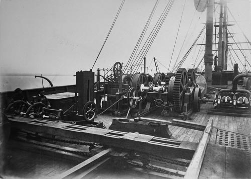
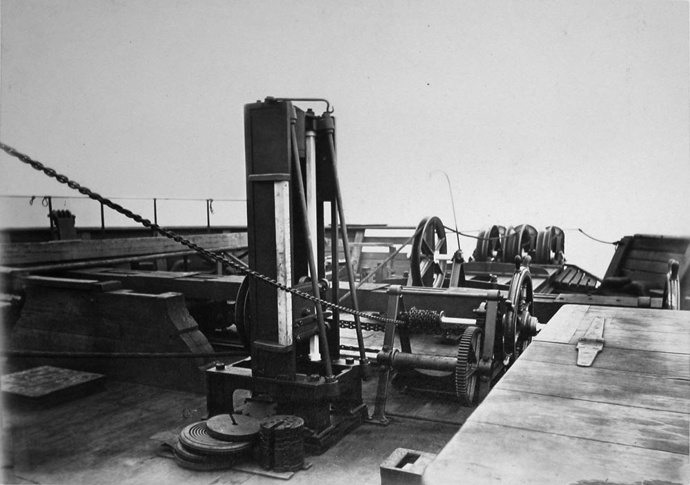
6. General View of paying out Machinery, seen from the stern of the Ship, showing the Cable, &c. as when being paid out.
Image courtesy of IET Archives |
The paying-out machinery was in principle identical with that used in the previous expedition of 1865, the only difference being that the frames of the machines were now made much stronger, as also the drums and their shafts, since they were constructed for picking up as well as paying out; many special arrangements were also made which fortunately were never called into requisition. Only one mishap of any importance occurred during the entire expedition, and that was when a large quantity of the cable fouled in the tank and came up all together on deck in the night of Wednesday 18th July, when about 700 knots had been laid. This entangled mass of cable was cleared after three hours' most exciting and anxious labour. The night was dark and raining, and a heavy summer gale was blowing; and only with the greatest care could the ship have been kept steady during so long a time. Evidently no appliances in the machinery could have been made to meet so extraordinary an occurrence. The ship was furnished with signal whistles, worked by air pressure constantly supplied from a steam engine, so that orders could be transmitted immediately and with the greatest precision to either the engine room or the bridges and steering deck; and probably the ultimate success of the expedition in no small degree depended on this arrangement.
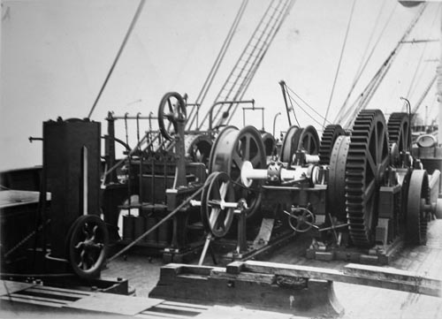
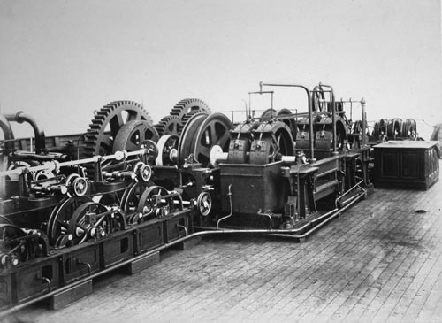
7. Sectional View of No. 6 so as to show the working parts of the Machinery on a larger scale.
Image courtesy of IET Archives |
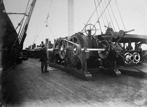
Daring the whole time of the paying out the machinery was most carefully watched at all points. The drums were fitted with rotometers, showing the amount of cable which had been paid out; and this amount was carefully noted every fifteen minutes in the ship's log, and the speed of paying out and the speed of the ship were calculated so that a right amount of slack might be allowed. If the ship were travelling too fast, the speed was immediately reduced in the engine room; and if too much cable was being paid away, a small addition to the weights on the drum breaks usually remedied this defect speedily: in fact the whole working of the machinery showed that every difficulty which presented itself was fully overcome. Varying winds and currents and many other circumstances caused constant watching from moment to moment to be increasingly necessary. When at length the shores of Newfoundland loomed in the distance and the laying of the Atlantic cable was at last a success, and when the electrical tests which had been constantly trying the condition of the cable proved that it had in no way whatever been injured by the machinery during fourteen days' constant working, then could all on board realise the success of so much labour and thought, the result of so many years of constant application and experiment.
Picking-Up Machinery.—Probably no course made by a vessel across the Atlantic was ever more definitely known and accurately marked on the chart than that made in the year 1865 by the Great Eastern during the attempt to lay the Atlantic cable. When the cable parted in that year, many days were spent in the attempt to recover it; this time was however by no means wasted, as the results then obtained proved not only the possibility but the certainty that the cable could be found and raised from the bottom. It was a bold experiment—that of grappling for a cable at the depth of two knots—and was altogether without precedent: sailors, engineers, and theorists had repeatedly declared it absurd; but the result of the actual trial of grappling proved at all events that it was not absurd, and showed that perhaps even the ultimate recovery of the cable was not hopeless. The difficult task of placing the ship in such a position that it should drift across the line of cable was three times successfully accomplished in the attempts made in 1865 to raise the cable; three times the cable was hooked, and three times the swivels in the rope failed. For days the dragging was determinedly continued by Sir Samuel (then Mr.) Canning, the engineer in charge of the expedition, until every fathom of rope was exhausted, and there was then no hope left for that year. Sufficient however had been done to render it impossible that other attempts should not be made; and all who were present were only more thoroughly convinced than ever that a cable could be laid across the Atlantic, and most sincerely believed that the cable commenced in 1865 would yet be recovered and finished. It matters not here to relate the exertions which were necessary for persuading capitalists to proceed yet farther in an undertaking considered by very many to be as impracticable as the search after the philosopher's stone; it is sufficient to know that the money was ultimately obtained, that the expedition was organised, and most important of all that it was successful. It is intended now to describe the means and the machinery by which this grand result was attained.
8. The picking up Machinery, situated near the bow of the Ship, showing the Grappling-rope round the Drum as when in use.
Image courtesy of IET Archives |
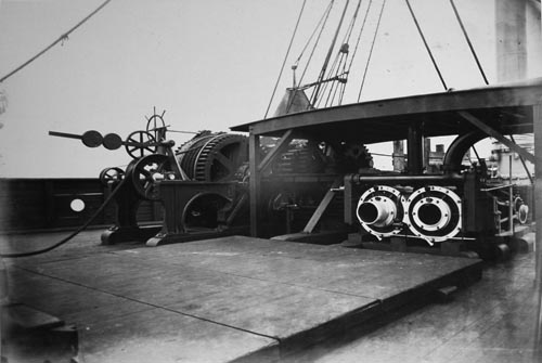
9. Same Machinery taken from the opposite side.
Image courtesy of IET Archives |
The cable of 1865 had been laid with about 15 per cent. of slack, and this percentage of slack was the great source of hope for the successful recovery of the cable. It was calculated that if the cable could be raised to the surface without hooking it at more than a single point, there would be a bight suspended in the water of 9¼ knots in length, when in 2 knots depth of water, as shown in the diagram, Fig. 5, Plate 2; and the horizontal distance J J would be 8 knots between the portions resting upon the ground, giving an excess of length of 15 per cent. in the suspended bight; and the results of the actual picking up proved this calculation to represent very closely the curve of the suspended cable. The size of the cable was 1⅛ inch diameter, and its weight 351 cwts. per knot in air, and 14 cwts. per knot when immersed in water; the total weight of a suspended length of 94 knots in water was therefore 6½ tons, but as the breaking strength of the cable was 7¾ tons, it would carry the weight of 11 knots of its own length in water before breaking. As however the possibility of its recovery in this manner in a single bight was generally considered to be out of the question, it was intended therefore to attempt raising it by degrees only. Thrée steamships were accordingly fitted with picking-up apparatus, the Medway, Great Eastern, and Albany, for the purpose of grappling for the cable simultaneously in three places: the Medway to grapple to the east and the Albany to the west of the Great Eastern.
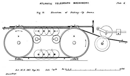
Plate 6 |
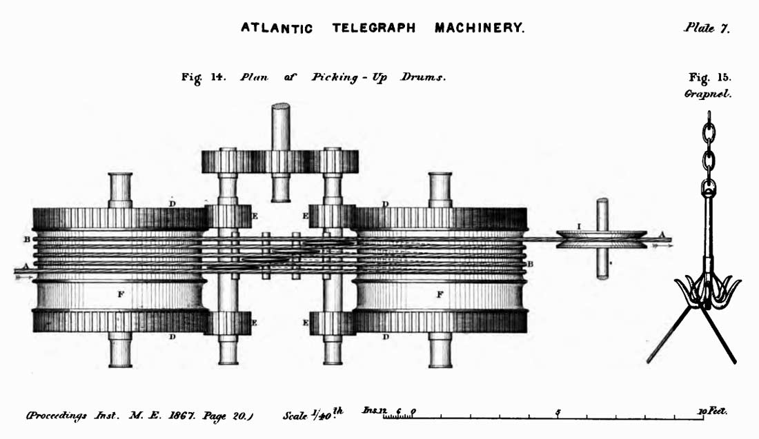
The picking-up machinery was entirely new for this expedition, and was constructed for a much greater strain than the machinery employed in the attempts of the previous year. The Grapnel, shown in Fig. 15, Plate 7, was simply a very large ordinary boat grapnel made with five prongs instead of three; it stood about 4 feet high, was fitted with a swivel at the top, weighed about 2¼ cwts., and its prongs would carry a strain of about 8 or 9 tons without damage. Shackled to this was a 15 fathoms length of 1⅛ inch chain, to which was fastened the grapnel rope. This rope was a most remarkable one, being 1⅞ inch diameter, and consisting of seven strands, six strands round one; each strand again consisted of six smaller strands of hemp, in the centre of each of which was a wire about 1-10th inch diameter. The rope was repeatedly tested, and was never known to break with less than 30 tons strain. Its weight in air was about 5 tons per knot, and in water 3¼ tons.
At the bow of the ship were fitted four iron girders carrying three cast-iron sheaves about 3 ft. 9 ins diameter; these sheaves were all clear of the ship, and over the centre one the grapnel rope was led on board, as shown at K in Fig. 2. The grapnel rope was led directly to the picking-up machine from the bow sheave, passing through a dynamometer so that the strain could be ascertained at all times. This dynamometer was similar to the one for the paying-out machinery described before, except that it was of a much heavier construction and loaded with a weight of 2142 lbs. The vertical travel of the dynamometer wheel was 5 feet, the horizontal length of deflected cable 30 feet, and the graduations of the scale ranged from 2 tons to 20 tons.

Plate 7 |
The Picking-Up Machine was very powerful, as it had to cope with a rope of 30 tons breaking strain, and if necessary to break it. It is shown in elevation and plan in Figs. 13 and 14, Plates 6 and 7. The two large drums B B, each 5 ft. 8 ins diameter, were fixed on shafts parallel to each other at 11 feet distance apart from centre to centre. The grapnel rope A A was passed four times round these two in the manner shown in Fig. 13, passing away on the opposite side from where it entered on. The fleeting of the rope was effected by small disc rollers C C placed on shafts between the drums, four above and four below; and each part of the rope was fleeted after leaving one drum before it entered on the other, thus keeping every portion of the rope clear of the rest. The fleeting required much more care in this machine than in the one for paying out, as the shackles and swivels on the grapnel rope would capsize on and hold down the preceding coil of the rope on the dram, unless the four coils were all kept very wide apart.
As the strains to which it was expected the machine might probably be put were very great, it was thought advisable not to take the power through the shafts of the drums B B; and accordingly the drums had spur wheels D D fixed at each side, into which the pinions E E geared; and by this means no torsional strain whatever was put on the shafts of the drums. The strain of the grapnel rope was divided thus between four spur wheels, and the pitch of these was only 4 inches; although in the paying-out machine, where this division of strain could not be effected, the spur wheels were 5 inches pitch. Each of the drums had a break F fixed to it, and both the breaks were worked by one shaft O O with two screws on it, carried fore and aft along the machine over the breaks. All the strain of the breaks was carried by brackets H H on the sole plate, and in no way by the screw shaft G; and this is believed to be rather a novel application of the break strap, and may be worthy of remark.
The machine was driven by a pair of trunk engines, precisely duplicates of the pair employed in the paying-out machine; and these engines, together with the picking-up machine itself, were made by Messrs. Penn. There was also a system of gearing similar to that belonging to the paying-out machine, for admitting of a change of speed and power; the slowest speed, when the engines made 80 revolutions per minute, was about ¾ knot per hour, and the quickest about 1½ knots per hour. The machine was supplied with a draw-off wheel I and jockey wheel J having an adjustable weight K, so as to keep the grapnel rope A well taut on the drums B; and a rotometer was added for measuring the length of grapnel rope overboard. When the picking up of the cable was in progress, the grapnel rope was delivered from the picking-up drums into the fore tank, which was at that time empty.
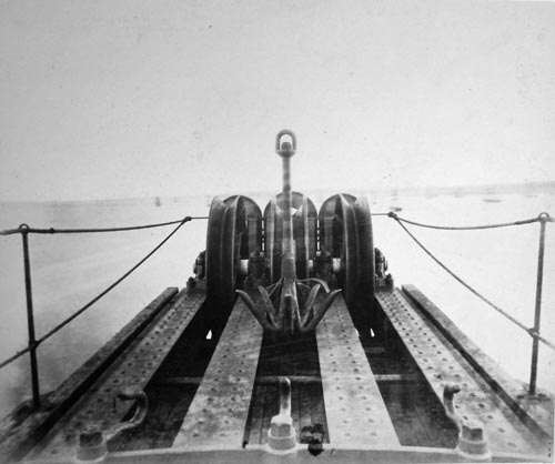
10. Showing the Bow-sheevs and the Grapnel-hook that brought up the Cable of 1865.
Image courtesy of IET Archives |
The process of grappling was as follows. The exact line of the cable having been marked by a couple of buoys put down by nautical observation, the ship was brought into a position about 3 or 4 knots north or south of this line, according to the direction of the wind and current, so that the ship might be drifted slowly across the line of the cable. The new cable of 1866 had been laid at a distance of about 30 knots southward of the line of the old cable, so as to avoid all risk of injury in the process of grappling for the old cable. In a depth of 1900 fathoms (nearly 2 knots), about 2200 fathoms length of grapnel rope with the chain and grapnel as before described was lowered with great care, taking about an hour or an hour and a half for the purpose. Whilst the grapnel was being lowered, accurate observations were continuously taken of the indications given by the dynamometer; and the grapnel striking the bottom was almost immediately indicated by a diminution of weight, as it and the chain weighed rather more than half a ton. About a couple of hundred fathoms of additional rope were then paid out, and the dynamometer from this time was most strictly watched; averages of the indications were taken every few minutes, and many hours frequently passed before there was the smallest change in these averages. It was interesting to observe how steadily these averages remained at about 8½ to 9½ tons, dependent upon the length of grapnel rope out, and the strength of the wind and current. An indicated rise of 5 cwts. was generally considered satisfactory evidence that the cable was once more hooked, and this seldom proved wrong; no attempt however was made to haul in the rope until the strain rose 2 tons above the average. As soon as a strain of 10½ to 12 tons was observed, the ship was brought up by her engines to ease the strain, and the operation of picking np commenced; the strain then generally rose to about 14 or 15 tons, and continued at this amount until the bight of the cable was raised off the ground, after which time it gradually lessened. The attempt was once made to raise this bight direct to the surface without assistance from the other ships, and it proved successful, the cable coming a few feet above the water with a strain of about 6½ tons. There was however a heavy swell on at the time, and the pitching of the ship broke the cable through.
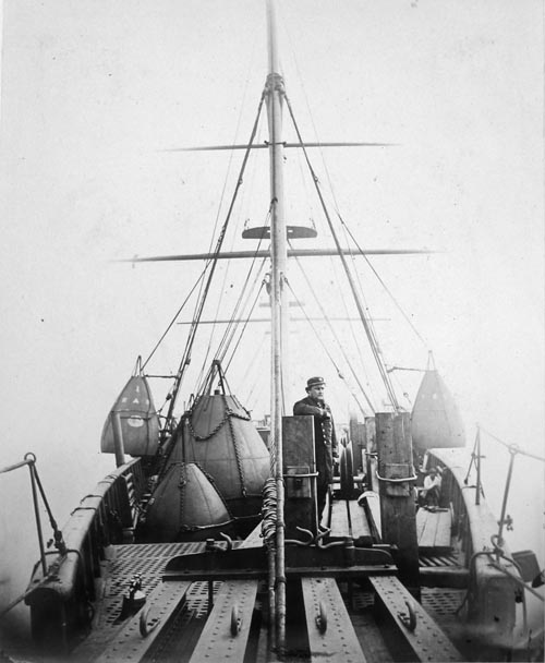
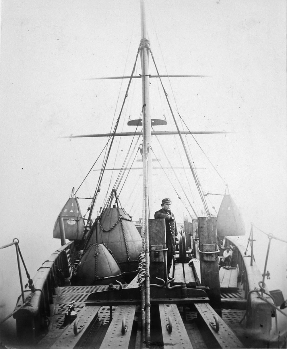
11. View from the bow, showing the Buoys, &c., especially the Large one, which floated with 13 tons weight attached.
Handwritten note: “The standing figure is Capt. Halpin”.
Image courtesy of IET Archives |
After many ineffectual attempts, the cable was at length successfully raised in the following manner. It was hooked by the Great Eastern, and the bight being raised about 900 fathoms from the bottom was buoyed there, as shown at B in Fig. 6, Plate 2: the buoy attached was of the largest size, weighing 3¼ tons, and capable of supporting a weight of 13 tons. The Great Eastern then again grappled for the cable about 3 or 4 knots westward at S, and again found it; the Medway found it at the same time at M, about 2 knots westward of the Great Eastern. The Great Eastern then commenced hauling in, signalling to the Medway to do the same, and to break it if she could not bring the bight to the surface; this she accordingly did, the cable breaking about 200 fathoms below the surface. The Great Eastern in this manner had a loose end of about 2 knots to the westward, and had immediately a much reduced strain to contend with. Ultimately the end was successfully brought on board, the electrical circuit to Valentia was once more established from the ship, and the movement of the small speck of light on the galvanometer scale by the current received from Ireland indicated the success of the undertaking. A shout of joy spread through the ship, the guns bellowed out the welcome news to the other ships; and the anxiety of nineteen days' continuous trial, which had culminated in an intensity that was most significantly betokened by the oppressive silence whilst the end of the recovered cable was being tested, now gave way to universal cheering and excitement.
The recovered end was speedily spliced on to the remaining portion of cable coiled in the tanks on board; and the ship was soon slowly proceeding onwards again with her head to the west. The paying-out machinery was from that moment all that possessed any interest; the picking-up dynamometer, which had been so constantly watched, was left deserted; and the hum of wheels, jockeys, and drums, was the sound most welcome to all on board. This fortunately continued without interruption until the ship's arrival the second time at Heart's Content, Newfoundland, thus completing the laying of the remaining 680 knots required to finish the original cable of 1865.
Specimens were exhibited of the new cable of 1866, and of the recovered cable of the previous year with the grapnel rope by which it was picked up, together with the original charts of the laying and picking up, which were lent for the occasion by the kindness of Captain Sir James Anderson.
Mr. C.W. SIEMENS considered they were much indebted for the very interesting and valuable particulars given in the paper respecting machinery which had been successful in achieving such an important work as the laying of the Atlantic telegraph cable, and which appeared in all its details to have been most carefully arranged. In the previous expedition of 1865 there was no doubt that a great mistake had been made in having the picking-up machinery separated by a distance of more than 600 feet from the paying-out machinery, the two being at opposite ends of the great ship; and this he considered had caused the loss of the cable in that attempt.
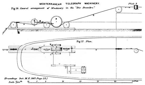
Plate 8 |
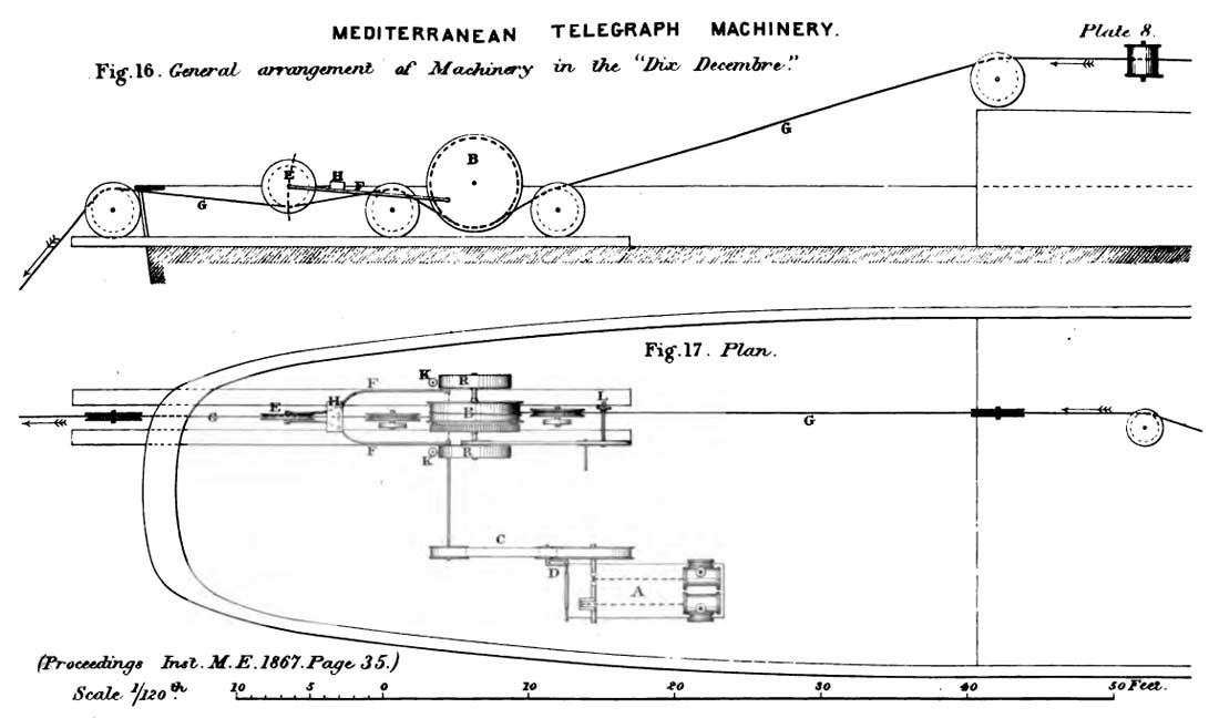
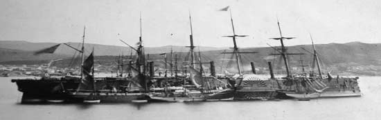
There was no occasion however for the use of separate machines for paying out and picking up, and machinery had previously been designed by himself for serving the double purpose of paying out and picking up (shown in Figs. 16 to 23, Plates 8 to 10), which was made by Messrs. Easton and Amos and fitted on board the Dix Decembre, a French telegraph ship that had done a great deal of actual service in laying and picking up telegraph cables in the Mediterranean. The engine A, Figs. 17 and 19, was placed on deck near the paying-out gear B, at the stern of the vessel; and the machinery was driven by the strap C tightened by the hand lever D, so that it could be thrown out of gear at any time. By this means he had frequently reversed the action of the machinery from paying out to picking up within only a minute or two, which he considered was a point of special advantage in such operations, by admitting of readily hauling in the cable for examination or repairs; for if any accident happened to the cable in paying out, such as any deficiency occurring in the electrical tests, it was most essential that there should be facilities for picking up the cable immediately and examining the injured place. In picking up by this arrangement, the vessel had of course to be drawn backwards by the strain upon the cable in being slowly hauled in; and in the case of a head wind this strain was diminished by working the ship's engines slowly in the backward direction. The Dix Decembre had been largely employed in picking up the Port Vendre and Minorca cable and other old Mediterranean cables, hauling the cable in at the stern, with most satisfactory results. If on the contrary in order to haul in the cable it had to be taken round along the whole side of the vessel from the stern to the bows, there was very great risk of injuring the cable, or of losing it altogether as occurred in 1865, because during the whole time of making the change the vessel was in effect riding at anchor upon the cable. He could only suppose that that mode of procedure arose from the old notion of sailors that the bows of a ship were the proper place for taking in a cable, because the anchor rope was always taken in at that end.
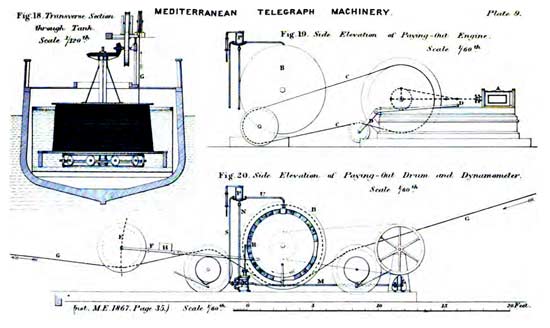
Plate 9 |
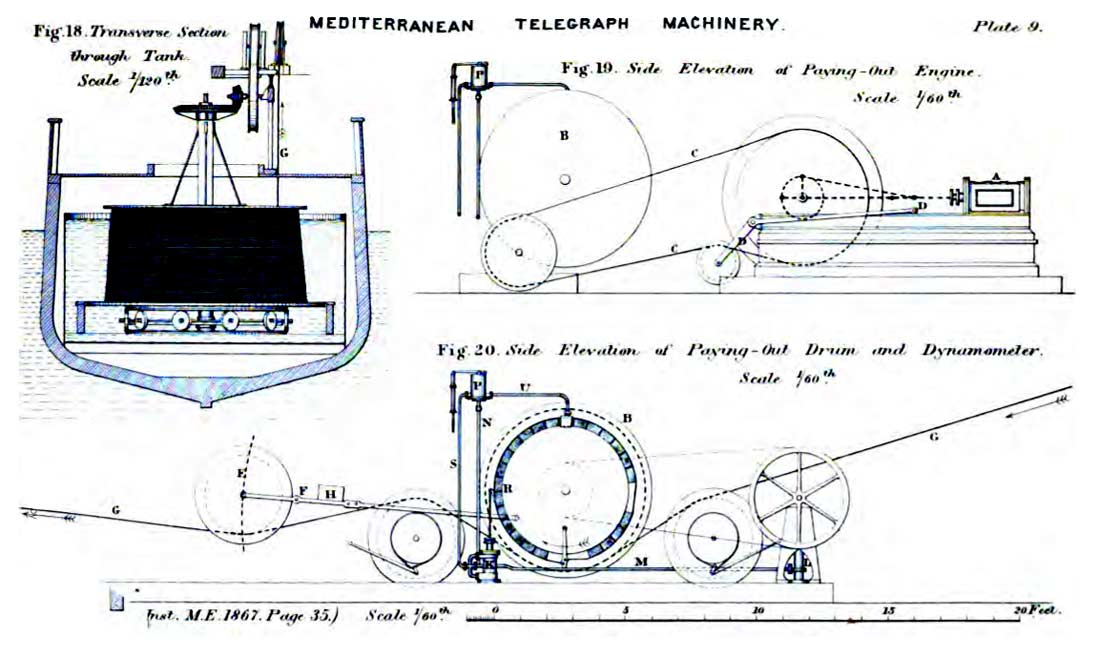
In paying out a cable, the dynamometer for showing continuously the strain under which the cable ran out was a most essential instrument, and in the arrangement described in the paper a weighted pulley working between guides rested upon the cable midway between two carrying wheels over which the cable passed. This construction however he thought was not so free in its action as the arrangement shown in Fig. 20, which he had adopted and had found completely successful, having the weighted pulley E carried at the extremity of a lever F, so that it rested freely upon the cable G; the lever was loaded either by a weight H, or by springs, the latter being preferable on account of their greater steadiness of action. A scale attached to the lever showed at all times the amount of strain upon the cable.
In place of loading the friction breaks of the paying-out drum by means of dead weights, as had previously been done, with the addition on the Great Eastern of water cylinders to prevent undue oscillation of the weights, as described in the paper, he had adopted a plan of loading the breaks which he thought had an advantage in delicacy and certainty of action, by the use of a hydraulic cylinder K, Figs. 20 and 21, loaded by a constant pressure of water upon the piston, according to a suggestion originally made by Professor Rankine and embodied in the design of the machinery on the Dix Decembre. The supply of water to the cylinder K was maintained by the pump L, Fig. 20, driven constantly by a strap from the shaft of the paying-out drum B; and the water being delivered along the pipe M communicated by the four-way cock I with the top of the break cylinder K, and passed up the rising pipe N to the regulating valve J in the tank P, shown to a larger scale in Fig. 22. The cylindrical casing of the valve J had four V shaped orifices, through which the water entering from the pipe N escaped continuously into the external tank P, the rate of escape being regulated by the position of the plunger J forming a piston valve, which was loaded by a spring-balance Q, like an ordinary safety valve. By this means a constant pressure was maintained upon the top of the piston in the break cylinder K, and the load upon the break R in paying out was thus readily adjusted by screwing the spring-balance Q to the desired pressure; while at the same time the load upon the break could never exceed the maximum to which the spring-balance was adjusted. The bottom of the break cylinder K communicated by the four-way cock I and the exhaust pipe S with the tank P, but outside the regulating valve J, so that the loading pressure was not conveyed to the underside of the piston in the break cylinder; and in order to allow of a slight amount of yielding in the hydraulic break, and to give it a sort of elastic action, the four-way cock I was itself made with a small hole through the plug, as shown to a larger scale in Fig. 23, through which a constant small leakage took place from the pressure side into the exhaust pipe. The break R was rendered self-relieving by the lever T, Fig. 21, in the same manner as described in the paper. There were two of the friction breaks R R, Fig. 17, one on each side of the paying-out drum B; and the two rising pipes N N from the break cylinders K K both entered under the same regulating valve J, Fig. 22, whereby the load was maintained always exactly equal upon both breaks. The water escaping from under the valve J into the tank P was delivered by a pipe U upon the top of each of the breaks for the purpose of lubricating them. When driving the drum B in the contrary direction, for picking up the cable, it was only necessary to reverse the four-way cock I; and the pressure then acting below the piston in the hydraulic cylinder K slacked the break strap off the break, while at the same time the lubrication by the waste water from the tank P continued undiminished, so that the drum B revolved freely without the action of the breaks.
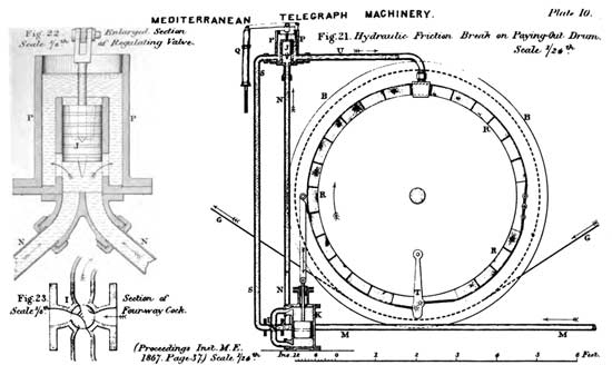
Plate 10 |
In the laying of the Atlantic cable he was glad to see that watertight tanks had been adopted for containing the cable on board the Great Eastern, as that was a measure which he had recommended for many years, because it preserved the cable from injury and allowed of a system of continuous tests during the whole time of the laying. In addition to the water-tight tank containing the cable in flakes or layers, an arrangement employed for light cables in the Dix Decembre was to carry the coil of cable upon a circular turntable revolving on a set of live rollers in the water tank, as shown in Fig. 18.
With regard to the grappling for the recovery of the cable of 1865, one fortunate circumstance connected with the Atlantic ocean was that its bottom appeared to be perfectly smooth and homogeneous. In the Mediterranean sea however, where he had grappled a cable at a depth nearly but not quite equal to that of the Atlantic, the circumstances had been much less favourable in those respects; and the dynamometer was therefore by no means so steady, but was liable to fly up suddenly to perhaps 15 cwts. and drop down again to 4 or 5 cwts., so that it was impossible to decide with such accuracy as in the Atlantic whether the cable was taken hold of by the grapnel or not. The reason no doubt was that the Mediterranean had a rocky bottom, full of coral formations in moderate depths, and rocky even at its greatest depths; whereas the bottom of the Atlantic appeared to be almost perfectly smooth. Another circumstance highly in favour of the Atlantic cable was that there seemed to be no animal life at the bottom of the ocean; whereas in the Mediterranean, if such a cable covered partially with hemp were put down to the bottom, it would be utterly destroyed in a few months by animals breeding upon the cable and eating up the hemp, leaving the wires unprotected and a mere burden upon the tender core. This had been the case with the early Candia and Chios cable and with the Toulon and Algiers cable laid in 1859, both of which had become entirely useless after being down, the former only six months, and the latter only about eight months. On the contrary the specimen now exhibited of the recovered Atlantic cable of 1865, which had been down at the bottom of the ocean for twelve months, was evidently as perfect as at the time that it was laid, although its construction was the same as that of the Toulon and Algiers cable. On all accounts therefore there seemed every reason to hope that the Atlantic cable now laid would prove a durable one.
Mr. W. FAIRBAIRN remarked that the laying of a cable across the Atlantic was one of the most important undertakings in ocean telegraphy; and having had an opportunity of inspecting the whole of the machinery a few days before the Great Eastern sailed on the last expedition, he considered it was most carefully constructed and arranged, so as to preclude any liability of mishap during the laying of the cable. The success that had attended the operation of laying the cable was mainly due in the first instance he thought to the use of the Great Eastern for conveying the cable, whereby the entire cable was contained in the hold of one vessel by means of the three tanks; so that by connecting these three lengths together in the vessel the entire cable was tested continuously during the whole process of laying it from Ireland to Newfoundland, and by this means any failure in the electric currents would have been instantly detected. The operation of paying out the cable had been admirably performed, as described in the paper, and the success with which it had been accomplished showed how well the machinery had been adapted for the purpose. Having made the experiments upon the tensile strength of the cable and also of the grapnel rope, he had found the results most creditable to the manufacture of both. One difference between the previous cable of 1865 and the new one of 1866 was that the former was coated with pitch, while the latter was left clean; and it had been found that in going over the pulleys of the paying-out machinery the grooves became so glutinous and sticky with the pitched cable that there was great difficulty in keeping them sufficiently clean; the new cable however without the pitch was paid out with the greatest possible ease, and this he thought contributed largely to the success of the laying. With regard to the destruction of the hemp covering by marine animals, even supposing the whole of the hemp were eaten off by them, the cable he believed would continue in complete working order, provided they did not attack the gutta-percha which formed the insulator. The outer covering of hemp appeared to him of very little importance or value after the laying of the cable had been accomplished, and so long as the insulator remained complete, he thought it would not be of fatal consequence if the whole of the outer covering were decomposed or eaten off. There appeared every reason to believe that the two cables now laid across the Atlantic, remaining perfectly quiescent at the bottom of the ocean, at so great a depth below the surface and under such a heavy pressure of water, might continue in perfect working order for a great number of years.
Mr. J.T. WRIGHT observed that he had been out to the Mediterranean a few months previously and had had an opportunity of examining a portion of one of the cables that had been raised for repairs; and it was found that, though the marine animals had destroyed the hemp, the cable remained electrically perfect and efficient wherever not damaged by excessive strain upon the core.
Mr. C.W. SIEMENS said he had seen the hemp covering of a cable entirely eaten away, and even the gutta-percha indented about 1-16th or 1-8th inch, but beyond that point the action of the marine animals did not appear to go. With regard however to the safety of the cable when deprived of its hemp covering, although it might continue efficient if lying upon a perfectly smooth bottom and with the tensile strain perfectly equalised throughout its length, yet that would certainly not be the case in the Mediterranean, where he was satisfied that as soon as the cable had ever worn weak at any point it would break, because the bottom of the sea was so uneven that the cable hung unsupported in a great many places. He had seen pieces of Mediterranean and Red Sea cables which had evidently given way at points of suspension by the rusting of the iron wires; and wherever the cable had parted, the core had been elongated several inches, and had shown electrical faults. Wherever the bottom was not perfectly smooth, the strains produced by the suspended portions of the cable must ultimately lead to fracture, if the iron wires became laid open to the action of rusting. So long as a cable retained its full strength, it was not indeed necessary that it should be perfectly supported throughout its entire length; but unless it were proved that the bottom of the Atlantic was so perfectly even that no portion of the cable would be in suspension, the continuance of the cable in working order must be dependent he considered upon the durability of the hemp covering protecting the iron wires from corrosion, which in the absence of marine animals might be for many years.
In addition to preserving the iron wires from rust, it must be borne in mind that the durability of the hemp covering was also essential to the strength of the cable, in consequence of the hemp acting as a packing to keep the wires at the proper distance apart. If the hemp were eaten away, the wires would be left like a loose cage round the core, and the latter would stretch and become faulty in consequence.
Mr. W. FAIRBAIRN had no doubt that in situations where the bottom of the sea was irregular, as in the Mediterranean and other volcanic districts, sharp points of rock would be met with where a cable would be carried by suspension in the manner that had been described; and he suggested that in such cases, where there was a liability of the hemp becoming abraded or eaten away by marine animals, an exterior covering of wires should be employed without hemp, so as to assist in preserving the full strength of the cable unimpaired by time. In the Atlantic however the apparently level character of the bottom led to the conclusion that no such difficulties would arise in connection with that cable; and with regard to marine animals, although they had been proved to exist in other seas at a depth of even 2 or 29 knots, it did not appear clear that any danger was to be apprehended at so great a depth at the bottom of the Atlantic. There seemed every reason therefore to expect that the Atlantic cable now laid would be as perfect after twenty or thirty years' work as at the present time.
Mr. E.A. COWPER thought there was no question that wherever marine animals existed they would eat away the hemp covering of such a cable as the Atlantic and would even attack the gutta-percha of the core; and as the sea water would exercise a corrosive action upon the iron wires as soon as the hemp covering was gone, it would become a mere question of time in such cases how long the cable would last. It was clear therefore that in such a sea as the Mediterranean, where the bottom was so irregular, and where animal life was known to exist down to the very bottom, it would be useless to attempt laying down a cable of the construction adopted for the Atlantic; and for such cases he considered the construction of cable designed and laid down by Mr. Siemens was well adapted, having the layer of hemp placed inside the cable, surrounding the core, while the external covering was formed of a sheathing of copper strips wound spirally on, whereby the cable was completely protected from the action of the water or the attacks of marine animals.
In reference to the description given in the paper of the grappling and raising of the previous cable of 1865, as shown in Fig. 6, it appeared that, after the cable had been first grappled and buoyed up at B to a height of about 900 fathoms from the bottom, the Great Eastern grappled it again further westward and raised it to the surface at S, where the splice was made, and the paying out then commenced of the additional length for completing the cable to Newfoundland; and he enquired whether the state of the cable had been examined at the bight B where it had been buoyed, and whether it exhibited any signs of injury from the grapnel pulling at it in that part.
Mr. F.G. WYNNE said that he had been on board the Great Eastern during the paying out of the new cable, and afterwards on board the Albany which grappled in concert with the two other ships. After the splice had been made at the point S where the cable had been raised to the surface, the paying out of the additional length for completing the cable had been proceeded with at once, and no examination had been made of the bight B where the cable had been grappled and buoyed, because the cable was proved to be electrically perfect; and there was no fear of injury having been occasioned to the outer covering, because the loose end brought up by the Albany showed only a very slight indentation where it had been hooked by the grapnel. The nautical observations taken in 1865 of the exact position of the broken end, though of great use in the first grappling for the cable in 1866, were not used in the final grappling, which was done 90 knots eastward of the first grappling; this was in order to avoid a deep depression in the bottom of the ocean, and also because the Albany had brought up a 22 knots length of cable to the eastward of the place where the Great Eastern had first grappled and raised the cable to the surface; and the examination of this piece proved that, even if the cable had been successfully raised where first grappled, there would have been no communication with Ireland. The westward end of the length brought up by the Albany was found to have the copper conductor corroded to a length of about 4 inch inwards from the end; and as this corrosion was no doubt due to the testing from Valentia, it showed that the cable must have been broken at that place in the previous year's operations, and the other end had no doubt been broken in the grappling of 1866.
In the paying out of the cable from the Great Eastern and the dragging with the grapnel, the successful working of the dynamometers was mainly due he thought to the steadiness of the ship itself; but even there the movement was so great when grappling in bad weather that it was often necessary to take averages of ten or twelve successive oscillations, in order to determine accurately enough the strain upon the grapnel rope. In the Medway and Albany however, on account of the smaller size of the vessels themselves, the dynamometers used to jerk up frequently through the whole range of the index from bottom to top, with such violence as to force the water out of the top of the water cylinder and render it useless, so that it had to be replenished with water at frequent intervals, sometimes every ten minutes.
In the new cable now laid across the Atlantic, the hemp covering was not left plain throughout the entire length, but there were several considerable lengths of it that were tarred. During the paying out of the untarred portion of the cable, temporary accidents in the tanks containing the cable were not unfrequent, owing he believed to projecting ends of wire catching in loose portions of the hemp covering of the adjacent coil; but in consequence of the care and promptitude of the men in instantly catching the lifted coil, only the one serious accident occurred that was mentioned in the paper. Loose ends of wire were also frequently detected by the scratching sound they made in running through the paying-out machinery. No such accident however that he knew of occurred with tha tarred portion of the cable, in which the tar seemed to close down completely the loose bights of hemp in the cable.
With regard to the question of animal life at the bottom of the Atlantic, he had seen three long conical shells, two of which were perfect, brought up from a depth of 2000 fathoms, having been entangled in the grapnel rope of the Albany; they were all apparently of the same species, but he believed there was nothing alive in them. It appeared that the grapnel rope must have passed through a considerable number of them, because the three brought up were within a few feet of one another on the rope. Specimens of the worm on which the codfish feeds were also met with at considerable depths on the grapnel rope, but these might have been caught upon the rope while hauling it up.
The PRESIDENT [John Penn] remarked that, having had to construct the picking-up machinery on the Great Eastern and the engines for driving it which were non-condensing, he had considered it important to make provision for extra security against the possibility of any undue strain ever coming upon the cable from any accidental increase of steam pressure in the engines, as they were of rather large power for the work they had to do. For this purpose he had added a very large safety valve upon the steam pipe, between the throttle-valve and the slide-valve chest, and this safety valve was loaded by a spring to the limit of pressure of steam intended to be supplied to the engines, 20 lbs. per square inch; a very long spiral spring was used, in order to obtain a great amount of elasticity, so that if the boiler pressure ever rose beyond the limit of 20 lbs., the excess of pressure would not be able to reach the pistons of the engines, but would be carried off by this large safety valve.
He proposed a vote of thanks to Mr. Elliot for the paper, which was passed.
1. Great Eastern S.S. entering Hearts Content Bay. Newfoundland. [detail]
Image courtesy of IET Archives |
See also:Recovery of the Lost Cable - 1866 |