 |
|
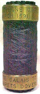
| The engraved
bands on the cable read: "Anglo-French Telephone Cable Submerged
March 1891" and "Sangatte Calais To St. Margarets Dover". |
The 1891 cable from St Margarets Bay, (Dover) England
- Sangatte (Calais), France, was manufactured by Siemens Brothers for the
GPO and laid by CS Monarch (2). It was the first cross-Channel telephone
cable, and the second cable on this route, the first being the 1851
Dover - Calais telegraph cable. Five further cables were laid on this route
between 1897 and 1945, all owned by the GPO.
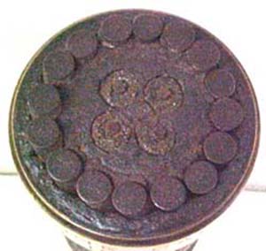
The 1891 cable had 16 armouring wires and the characteristic
four conductors of a telephone cable, each conductor consisting of seven stranded wires. As noted below, this provided two telephone circuits.
In his 1898 book, Submarine Telegraphs, Charles Bright provides this description of the 1891 cable:
LONDON-PARIS TELEPHONE LINE
From what has preceded it will be seen that the question as to whether a telephone circuit could be satisfactorily established between London and Paris was not by any means one which could be settled off-hand. Thus, no little credit is due both to the French and English Government officials—and especially to Mr Preece—who carefully went into the matter before it was a fait accompli, by the greatest city in the world being put into telephonic communication with the gayest.
The idea of connecting London with Paris by telephone first emanated from the French people. M. Coulon, who was the Minister of the French Administration des Postes et Télégraphes, thought telephonic connection both feasible and desirable, and communicated with the authorities at St Martin's-le-Grand upon the subject. Having been proved experimentally by them to be scientifically possible, the Treasury made no difficulty in coming forward with the necessary funds.
This undertaking was actually carried out in 1891—fifteen years after the invention of the telephone— and was the first instance of submarine—or rather partially submarine—telephony being established. [1] Though, of course, only on a small scale, it has proved entirely satisfactory, and up to, or even beyond, all expectations.
Inasmuch as the London-Paris telephone circuit would be partly composed of aerial wire (at each end) and partly (in the middle) of submarine cable, a number of experiments were tried with various types of overhead wires applied to artificial copies of the electrical components of different types of submarine cable in order to arrive at what would give the best result.
In Mr Preece's experiments he found that speech would be good on an overhead copper wire if the KR did not exceed 10,000, on an overhead iron wire if the same did not surpass 5,000, and on a submarine cable or underground wire if it be within 8,000. This last figure, in fact, determines the design of a telephone cable—i.e., the type of conductor and the thickness of its insulation—just as the previous figures determine that of an aerial telephone line according to the metal used. Iron is clearly unsuited for long, or trunk, telephone lines, because its specific KR is so large, and, in fact, it is never employed except on short, or exchange, circuits. Copper, having a low electrical resistance, is used for long trunk lines and cables.
The total distance from London to Paris by the railway routes on each side is 271 miles, comprising 70 miles from London to Dover, 21 miles from Dover to Calais, and 180 miles from Calais to Paris. The loop circuit being essential, the length of wire needed is, of course, twice 271, or 542 miles, including 42 miles of submarine core. It was decided on each side to make two separate land lines with a common cable of four conductors, the joint property of both Governments. The English land lines are of copper wire, weighing 400 lbs. to the mile; the French are of the same material, but of a gauge represented by 600 lbs. per mile. In both cases the wires are elevated on poles 30 feet above the ground.
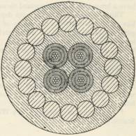
The connecting cable, as designed by Mr Preece and his assistant, Mr H.R. Kempe, contains four separate insulated wires, or cores, each consisting of a strand of seven copper wires (each wire being 35 mils. in diameter), weighing 160 lbs. per N.M. The above stranded conductors are individually coated with three layers of gutta-percha alternated by Chatterton's compound. The dimensions of this dielectric are represented by a weight of 300 lbs. per N.M., bringing the total weight of each core (conductor and dielectric) up to 460 lbs. per N.M., and the diameter to 390 mils.
The copper used for the conductor is of the very purest obtainable for yielding the highest specific conductivity possible.
The resistance of each conductor in the cable is about 7.5 to 7.6 ohms per N.M. at a temperature of 75° F. The capacity for induction of each N.M. of core does not exceed 0.305 microfarads, its insulation being not less than 500 megohms at 75° F.
The four cores, as above described, are laid up together, wormed by a serving of tanned hemp; and the diagonal pairs are used together in the same metallic circuit. The cable sheathing consists of sixteen galvanised iron wires, of 280 mils. diameter, their individual strength being represented by a breaking strain of 3,500 lbs.—or over 1½ tons.
The London-Paris
Telephone Cable |
An illustration of the cable—which was constructed by Messrs Siemens Brothers—is given here. It was laid by H.M.T.S. "Monarch" and the Post Office officials in March 1891, when the heavy snowstorm and other inclement weather then in force greatly interfered with the operations. The length of the cable is 20 N.M.: it extends from St Margaret's Bay, near Dover, to Sangatte, near Calais. The land lines on each side had already been completed by the French and English Governments respectively.
The total length of the line is 311 English miles.
The copper resistance of each metallic circuit is 1,380 ohms; and its capacity (calculated) 5.3 microfarads. The total KR is, therefore, 7,314, which brings the circuit well within the limit of good speaking as defined by Mr Preece.
The instruments used in London are the usual Post Office telephones, each being fitted with two double-pole Bell receivers. In Paris, the Ader, the D'Arsonval, and other telephones are used, subject to the approval of the French Administration.
The first circuit was opened to the public on 1st April 1891, the traffic being considerable from the outset—in fact, more than could be dealt with on a single circuit. In February 1892, the second circuit was thrown open for traffic, and both circuits are now always fully occupied.
The present charge for a conversation of three minutes' duration is 8s. [2] The line is largely used by members of the London Stock Exchange and Paris Bourse [3], as well as for Press work and general commercial purposes, both circuits being always open day and night. The average number of messages per day (on the two circuits) is about 250.
This telephone line has since been followed by another [4] in 1893 between Scotland and Ireland (Glasgow to Belfast), and there is a further prospect of our being put into telephonic communication with Brussels and Berlin.
In spite of the electrical difficulties of the problem, inventors and experimenters are constantly engaged in endeavouring to better these beginnings, and even hold out some hope of some day talking to America by telephone.
For full information regarding the whole subject of telephony, the
reader is referred to Messrs Preece and Stubbs' excellent treatise thereon. [5]
Notes:
[1] In 1889 the telephonic system of France came into the hands of the Administration des Postes et Télégraphes. The English Post Office and the above French Administration in that year purchased, as a joint property, the Channel cables of the Submarine Telegraph Company, and their next step was, as stated above, to project a telephone line and cable from London to Paris.
Mr Preece had just designed a river cable to cross the estuary of the La Plata and connect the cities of Buenos Ayres and Montevideo by telephone. This cable was 28 miles long, but the bronze overhead wires brought the length of the entire line to 186 miles and the KR to 10,400. The speaking attained on this line is, however, very good.
[2] Two consecutive periods of three minutes may be arranged for; but in no case can more than six consecutive minutes be allowed, except during slack portions of the day; and then only by arrangement at the time of application for a conversation, and on the understanding that if the line is required at any time after the expiry of six minutes it will be taken. The line cannot be pre-engaged. It is customary for users to either write or telegraph to their correspondents to be in attendance at a certain time, and then wait their turn.
[3] Thus during the middle portion of the day the traffic is heavy, and users of the line occasionally have to wait a short time for their opportunity.
[4] The submarine cable in circuit here is of precisely the same pattern in every respect as the Anglo-Continental cable just described, except that the served and wormed cores have a brass tape sheathing round them.
This is in order to cope with the depredations of the Limnoria terebrans—a mollusc-like worm distinct from the teredo of the Eastern seas. It has a predilection for the gutta-percha as well as the hemp serving, and has been found within recent years to infest even these (non-tropical) waters. This is possibly owing to cables from the tropics being brought home in the course of repairs, and the germs being communicated at cable factories; indeed, the core is often resheathed for second use.
Thus, since 1893 it has been the custom with the Post Office to apply metal taping to the core of all Post Office cables. It is also partly on this account that the Department always specify hemp instead of jute for the inner serving; though it may be doubted whether the former withstands the ravages of submarine borers any better than the latter.
[5] “Manual of Telephony," by William Henry Preece, C.D., F.R.S., and Arthur J. Stubbs (Whittaker and Co.).
A paper by Major W.A.J. O'Meara read on 15 December 1910 at a meeting of the Institution of Electrical Engineers in London gave these details of the 1891 cable:
SHORT DESCRIPTION OF THE FIRST ANGLO-FRENCH
TELEPHONE CABLE.
Opened to the Public April 1, 1891.
This was a 4-core cable differing out little from those in use at the time for telegraphic purposes, except in the size of the cores. Each core consisted of a stranded copper conductor formed of 7 equal wires, having a total weight of 160 lbs. per knot, covered with 300 lbs. of gutta percha per knot. The extreme diameters of the copper strand (d) and of the gutta percha covering (D) were 0.108
and 0.390 in. respectively, giving a ratio D/d = 3.61.
The measured resistance of the conductor at 75° F. was 7.453 ohms, and the measured electrostatic capacity 0.275 microfarad per knot. The sheathing consisted of 16 galvanised iron wires, each 0.280 in. in diameter, put on with a lay of 18 in., and the external diameter of the finished cable was about 2.2 in.
|
